dont be afraid
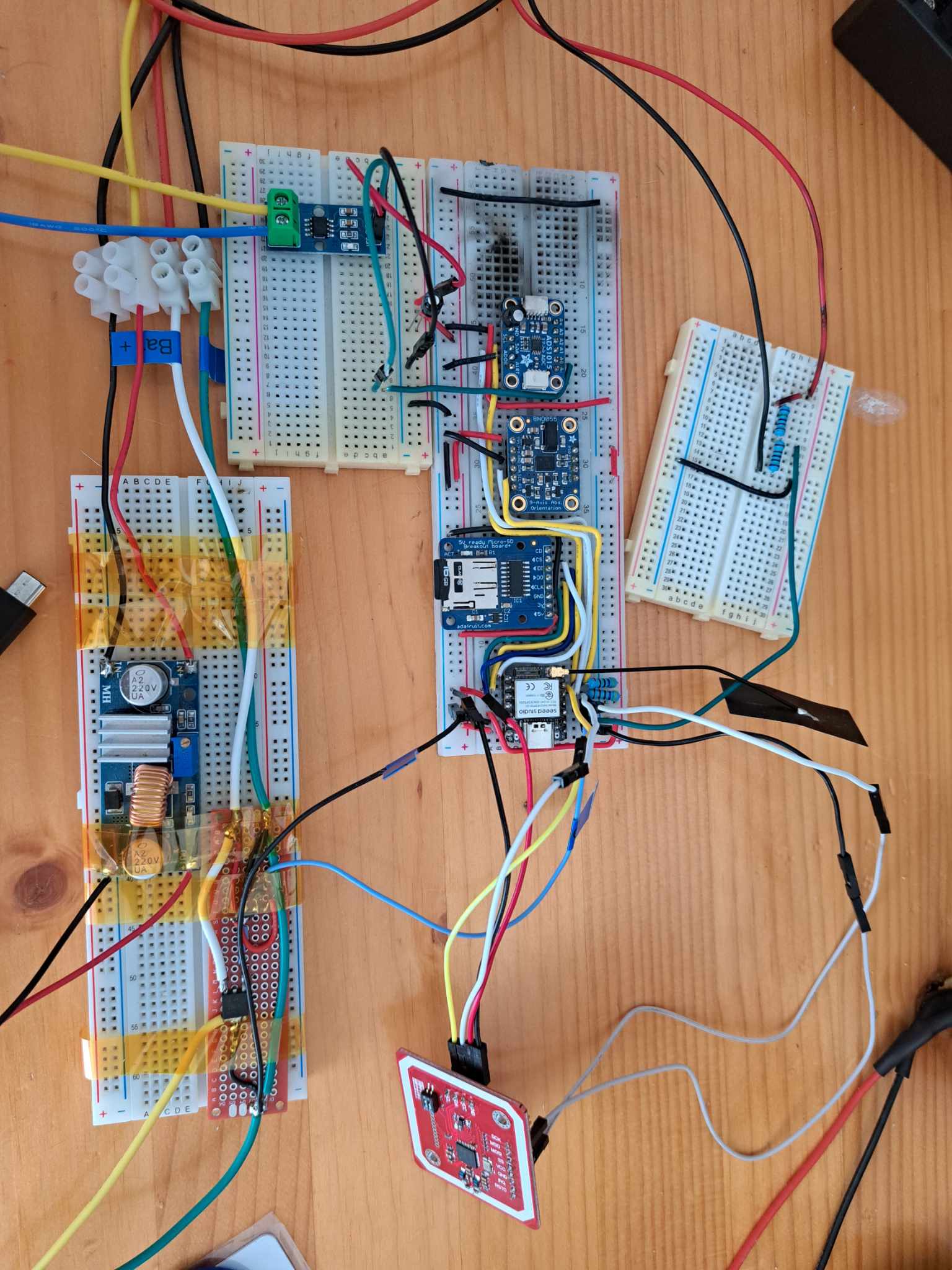
try to show close up of the wire connections
too big for what im striving for but thanks
Hi there,
He’s trying to use 2 instance of Wire LIB. second one he’s naming the pins is all. Sti;l A4 & A5
totally legit. If you doit correctly and the version Supports it.
HTH
GL ![]() PJ
PJ ![]()
at least im legit ![]() what should i do doctor ?
what should i do doctor ?
read and look at this ESP32 I2C Communication: Set Pins, Multiple Bus Interfaces and Peripherals | Random Nerd Tutorials
ESP32 Using Two I2C Bus Interfaces
To use the two I2C bus interfaces of the ESP32, you need to create two TwoWire instances.
TwoWire I2Cone = TwoWire(0);
TwoWire I2Ctwo = TwoWire(1)
Then, initialize I2C communication on your desired pins with a defined frequency.
void setup() {
  I2Cone.begin(SDA_1, SCL_1, freq1);
  I2Ctwo.begin(SDA_2, SCL_2, freq2);
}
I notice you don’t specify a clk freq?
HTH
GL ![]() PJ
PJ ![]()
The ESP32-S3 supports Inter-Integrated Circuit (I2C) Standard-mode (Sm) and Fast-mode (Fm) with frequencies of up to 100 kHz and 400 kHz, respectively. The frequency of SCL is affected by both the pull-up resistor and the wire capacitance, so it’s recommended to choose the right pull-up resistors to ensure an accurate frequency
Hi there, Something like this setup for two BME280’s
#include <Wire.h>
#include <Adafruit_Sensor.h>
#include <Adafruit_BME280.h>

#define SDA_1 4
#define SCL_1 5

#define SDA_2 33
#define SCL_2 32

TwoWire I2C_1 = TwoWire(0);
TwoWire I2C_2 = TwoWire(1);

Adafruit_BME280 bme1;
Adafruit_BME280 bme2;

void setup() {
  Serial.begin(115200);

  I2C_1.begin(SDA_1, SCL_1, 100000ul);
  I2C_2.begin(SDA_2, SCL_2, 100000ul);

  bool status1 = bme1.begin(0x76, &I2C_1);
  if (!status1) {
    Serial.println("Could not find a valid BME280_1 sensor, check wiring!");
    while (1);
  }

  bool status2 = bme2.begin(0x76, &I2C_2);
  if (!status2) {
    Serial.println("Could not find a valid BME280_2 sensor, check wiring!");
    while (1);
  }

  Serial.println();
}ode here
HTH
GL ![]() PJ
PJ ![]()
its called prototyping… you have to prove the concept before you can miniturize
Hi there,
Can you paste the first 3 lines of the compiler output window? and maybe add the last 8-9 lines before the upload.
Do you know how to do that?
GL ![]() PJ
PJ
nop, can you teach me ?
yeah i know, thats why i use breadboard
i tried alot of this stuff with no success but surely, i dont implement it correctly. I will retry tomorrow. thanks alot for your patience and your help !
also, in your example they declare the bme constructor without any pins, something you cant do with the pn532. So, if you declare , irq, reset and add two other pins for sda and scl you sort of need 4 pins no ?
Hi there,
No what type of device is it, LIKE a display you only write to it Commands & Data nothing comes back, Ie. the display doesn’t send anything back.
In the case of an NFC shield its a command to write the NFC tag and the command to read the data when a tag is with x centimeters.
The device also supports a HSU (High Speed Uart) interface and SPI as well.
How do you have it connected? post a picture if possible.
is it which one of these?
GL ![]() PJ
PJ ![]()
I think it is important to go with Seeed Gear whenever possable… i dont think he is even using seeed gear because he refuses to post any pictures… the first problem is assuming seeed programming will run on Adafruit devices… What Da?
most of my stuff is adafruit and its runs perfectly with seeeduino. i dont see a problem and no, its not the seeeduino shield, its the one from elecrow you posted earlier. None of the library they suggest works too. Alll depedency problem
using this example from the library
/**************************************************************************/
#include <Wire.h>
#include <SPI.h>
#include <Adafruit_PN532.h>


// If using the breakout or shield with I2C, define just the pins connected
// to the IRQ and reset lines.  Use the values below (2, 3) for the shield!
#define PN532_IRQ   (D9)
#define PN532_RESET (D6)  // Not connected by default on the NFC Shield

const int DELAY_BETWEEN_CARDS = 500;
long timeLastCardRead = 0;
boolean readerDisabled = false;
int irqCurr;
int irqPrev;

// This example uses the IRQ line, which is available when in I2C mode.
Adafruit_PN532 nfc(PN532_IRQ, PN532_RESET);

void startListeningToNFC();
void handleCardDetected();

void setup(void) {
  Serial.begin(115200);
  while (!Serial) delay(10); // for Leonardo/Micro/Zero

  Serial.println("Hello!");

  nfc.begin();

  uint32_t versiondata = nfc.getFirmwareVersion();
  if (! versiondata) {
    Serial.print("Didn't find PN53x board");
    while (1); // halt
  }
  // Got ok data, print it out!
  Serial.print("Found chip PN5"); Serial.println((versiondata>>24) & 0xFF, HEX);
  Serial.print("Firmware ver. "); Serial.print((versiondata>>16) & 0xFF, DEC);
  Serial.print('.'); Serial.println((versiondata>>8) & 0xFF, DEC);

  startListeningToNFC();
}

void loop(void) {
  if (readerDisabled) {
    if (millis() - timeLastCardRead > DELAY_BETWEEN_CARDS) {
      readerDisabled = false;
      startListeningToNFC();
    }
  } else {
    irqCurr = digitalRead(PN532_IRQ);

    // When the IRQ is pulled low - the reader has got something for us.
    if (irqCurr == LOW && irqPrev == HIGH) {
       Serial.println("Got NFC IRQ");
       handleCardDetected();
    }

    irqPrev = irqCurr;
  }
}

void startListeningToNFC() {
  // Reset our IRQ indicators
  irqPrev = irqCurr = HIGH;

  Serial.println("Starting passive read for an ISO14443A Card ...");
  if (!nfc.startPassiveTargetIDDetection(PN532_MIFARE_ISO14443A)) {
    Serial.println("No card found. Waiting...");
  } else {
    Serial.println("Card already present.");
    handleCardDetected();
  }
}

void handleCardDetected() {
    uint8_t success = false;
    uint8_t uid[] = { 0, 0, 0, 0, 0, 0, 0 };  // Buffer to store the returned UID
    uint8_t uidLength;                        // Length of the UID (4 or 7 bytes depending on ISO14443A card type)

    // read the NFC tag's info
    success = nfc.readDetectedPassiveTargetID(uid, &uidLength);
    Serial.println(success ? "Read successful" : "Read failed (not a card?)");

    if (success) {
      // Display some basic information about the card
      Serial.println("Found an ISO14443A card");
      Serial.print("  UID Length: ");Serial.print(uidLength, DEC);Serial.println(" bytes");
      Serial.print("  UID Value: ");
      nfc.PrintHex(uid, uidLength);

      if (uidLength == 4)
      {
        // We probably have a Mifare Classic card ...
        uint32_t cardid = uid[0];
        cardid <<= 8;
        cardid |= uid[1];
        cardid <<= 8;
        cardid |= uid[2];
        cardid <<= 8;
        cardid |= uid[3];
        Serial.print("Seems to be a Mifare Classic card #");
        Serial.println(cardid);
      }
      Serial.println("");

      timeLastCardRead = millis();
    }

    // The reader will be enabled again after DELAY_BETWEEN_CARDS ms will pass.
    readerDisabled = true;
}saisissez ou collez du code ici
i was able to get once : Hello!
Found chip PN532
Firmware ver. 1.6
Starting passive read for an ISO14443A Card …
No card found. Waiting…
couple of try after, i got : Got NFC IRQ
Read successful
Found an ISO14443A card
UID Length: 4 bytes
UID Value: 0x63 0x13 0x7B 0xFA
Seems to be a Mifare Classic card #1662221306
Starting passive read for an ISO14443A Card …
No card found. Waiting…
i connected IRQ to D10 because, right now, im not using the microSD module and connected Rsto to D6, SDA to SDA and SCL to SCL
its seems intermittent…
Hi there,
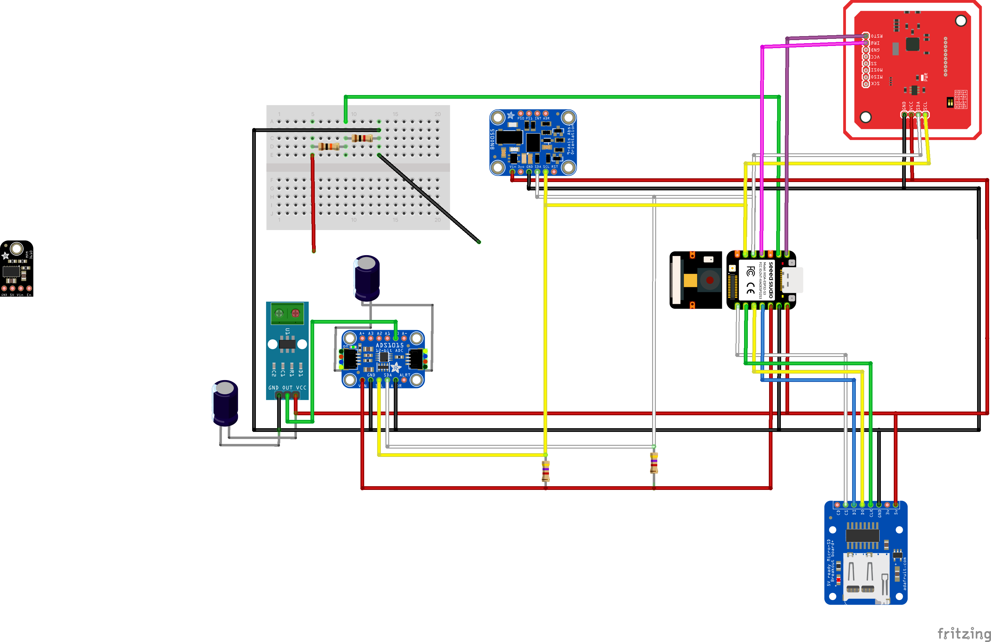
OK Nothing jumps out at me from the schematic,
Looks However the PN532 is set for HSU in the picture?(should be I2C)
Your Chip Select is GPIO4,and your looking for IRQ on GPIO1
SD card r/w is Gpio44 for CS.
GPIO2 is for sensing the VIN , not connected or what?
Post your PL.IO ini file.
You probably need to use GPIO numbers. and I’m betting an OLDER BSP for the Xiao, Those libs may not be compatible with 3.0.2 (the latest one)
Verify the above.
HTH
GL ![]() PJ
PJ
![]()
post the first three lines of the compiler output… ![]()
it will work if EVERYTHING is on point. Verify you have 5V and 3.3v also. The GND’s look ok.
but i2c is SDA to D4 and SCL to D5 no ?
could you send a reference for the gpios im confused
whats gpio2?
heres my pl.io ini file :
[env:seeed_xiao_esp32s3]
platform = espressif32
board = seeed_xiao_esp32s3
lib_deps =
fbiego/ESP32Time@^2.0.4
arduino-libraries/NTPClient@^3.2.1
framework = arduino
monitor_speed = 115200