I’m building a BLE controller with the XIAO ESP32-C6 and a 3.7V LiPo battery that will pair with another device with BLE. I want the controller to be USB rechargeable by taking advantage of the XIAO’s onboard battery charging circuitry. Since the goal is to make the system portable and efficient, I plan to use a 3.7V LiPo battery due to its slim profile and better form factor for compact designs.
The device includes multiple push buttons connected to GPIOs, and I want to repurpose one of these buttons to act as both a functional input and a power ON/OFF switch. However, I want more than just putting the ESP32 into deep sleep. I want to fully cut off power to the ESP32-C6 when the device is OFF to ensure zero current draw, extending battery life during inactivity.
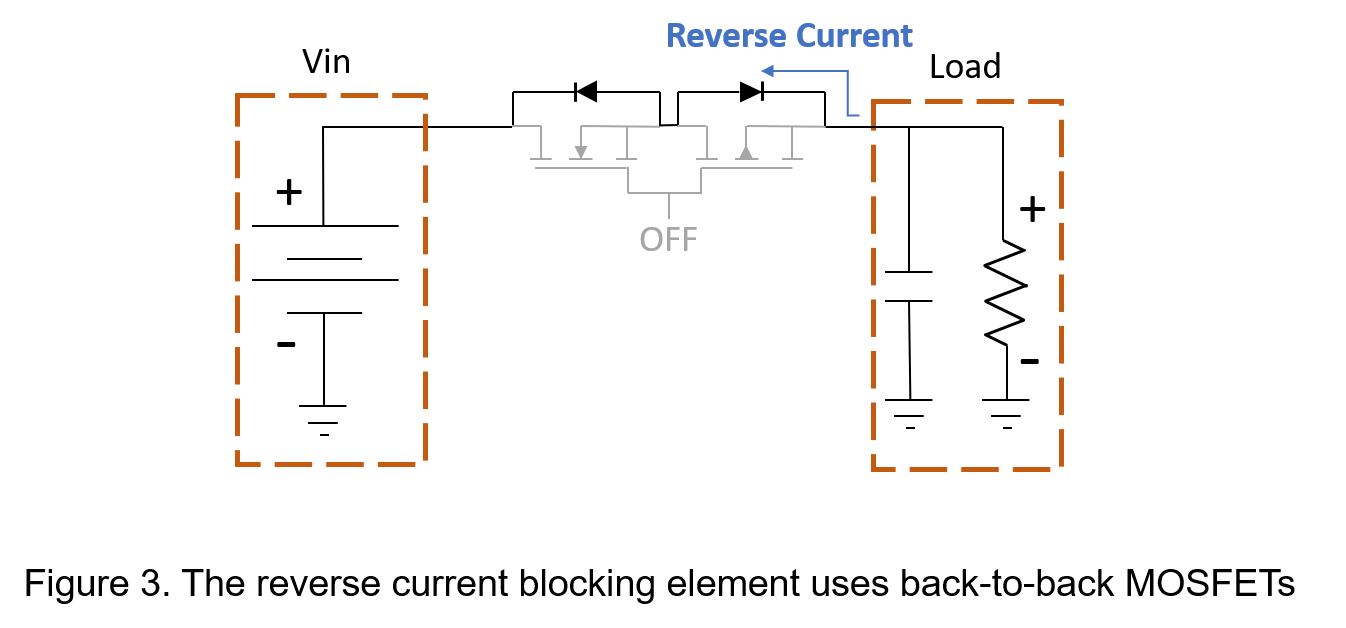
I’m exploring hardware and software level solutions that allow a button press to turn ON the device (e.g., using a MOSFET latch or load switch or any other than deep sleep), and later allow the microcontroller to cut its own power via GPIO once the user wants to switch off or for a long time no activity is detected when the system goes in power off mode automatically. Importantly, I want the same button to continue acting as a normal input when the system is ON—e.g., to trigger actions or modes. So, we can repurpose the duration of button presses like short or long presses to detect intention of usage.
I’m also considering the role of battery size here: I want enough capacity for decent runtime, but I also need to keep the battery physically small to maintain a slim profile. The generic market 3.7vLiPo batteries with around 55mAh capacity seems a size that can fit in the dimensions we intend on first inspection. However, we are not sure if there are minimum capacity requirements for Xiao ESP32-C6 as well. So, we need some inputs on the minimum battery capacity supported for the 3.7v LiPo battery by Xiao C6.
Summary
1.What is the ideal LiPo battery capacity recommendation for such a compact device?
2.What is the most effective and space-efficient method to implement a full power cut-off using a GPIO-controlled circuit (like MOSFET, latch, or load switch), while still allowing a button to serve dual functions?
3.Are there any better alternate techniques or off-the-shelf modules to manage the power ON/OFF functionality for battery-powered XIAO ESP32-C6 systems?
- In this post on this forum I also read that c6 does not have discharge protection. Is it true? because I thought all XIAO battery support boards always have the charging protection on board for battery operation.
5.Whats the minimum 3.7v LiPo battery capacity in mAH recommended to be used with XIAO ESP32-c6?
Hi there,
So this type of project has been worked on before here. You can find some posts that describe a similar use case.
I can address what I know on your points. Others will chime in and give you there thoughts as well.
- Physical size is always the limiting factor. But normally you would base line you r power requirements, Know what your operating current profile is and sleep profile too. Then given a power consumption current draw for this unit , use the Battery Size calculator https://www.digikey.com/en/resources/conversion-calculators/conversion-calculator-battery-life to get the days vs. power used info and some recommended sizes.
- Primoni makes that for the PICO board, it’s a small pcb that connects to the bottom like a sandwich, You end up with a small button under the USB-C connector that is I/O connected too and a long press powers-off the device and a single press when off , powers it back on. I wanted to make one for the Xiao it would work on all of them. the Schematic is online also. just no time to do it. (seeed should have that)
- (see #2)
 I had the link but can’t find it atm…
- NO , that is a function of the Battery Management System on each Lipo. OVER/UNDER and temp shut-off.
Xiao only stops charging at level and has minimum level for power-up.
- Due to the WIFi and BLE I rarely see less than a 450mah rated battery used. YMMV (really depends on your resulting power profile for the whole device.)
HTH
GL  PJ
PJ 
be sure to check out @msfujino (power ninja) posts on the Xiao Family battery and power profiles for sleep and Deep sleep. 
Thank you, PJ, for your time and efforts.
From Point 2
[LiPo SHIM for Pico]
I found this link with the said product you mentioned. Could you please confirm if it’s the same product you mentioned?
And if yes, as you said, this one is for pico board, while you planned to make one for XIAO but never made it, but I should
be able to find the schematics or some design on SEEED somewhere.
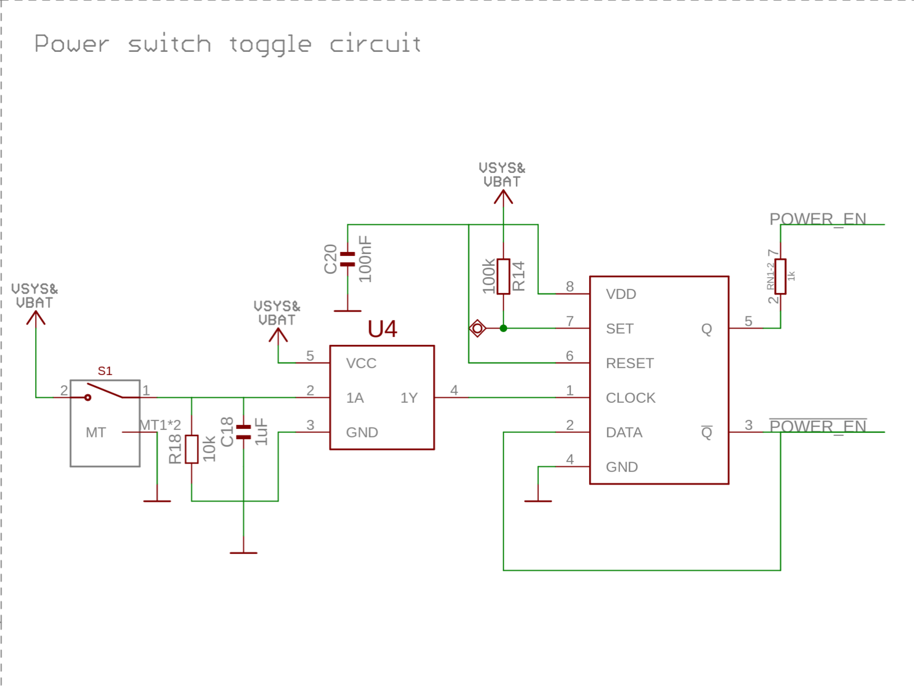
I found this link for the above product schematics?>CKT Digram
Does this look correct?
For xiao board itself, do you have any suggestion where can I find that design / schematics that could be suitable for XIAO boards please? Or it can be further inspired from the schematics
I found for pico by suitable modifications?
From point 4
I am trying to analyse battery usage based on product usage approximately, and will come back on that a bit later once I have worked further on it to get your thoughts about it for
suitable battery capacity related inputs.
Further I was also wondering, if I were to just add a simple battery on/off switch on PCB in simplest way will that work for power on/off requirement?
Though it will take up space on the PCB.
Or is there any other better ways that could be simpler for power on/off requirements? Any feedback will be great to have.
Thanks again for your time and support PJ. Highly appreciated.
I wish Seeed would focus on this power management area
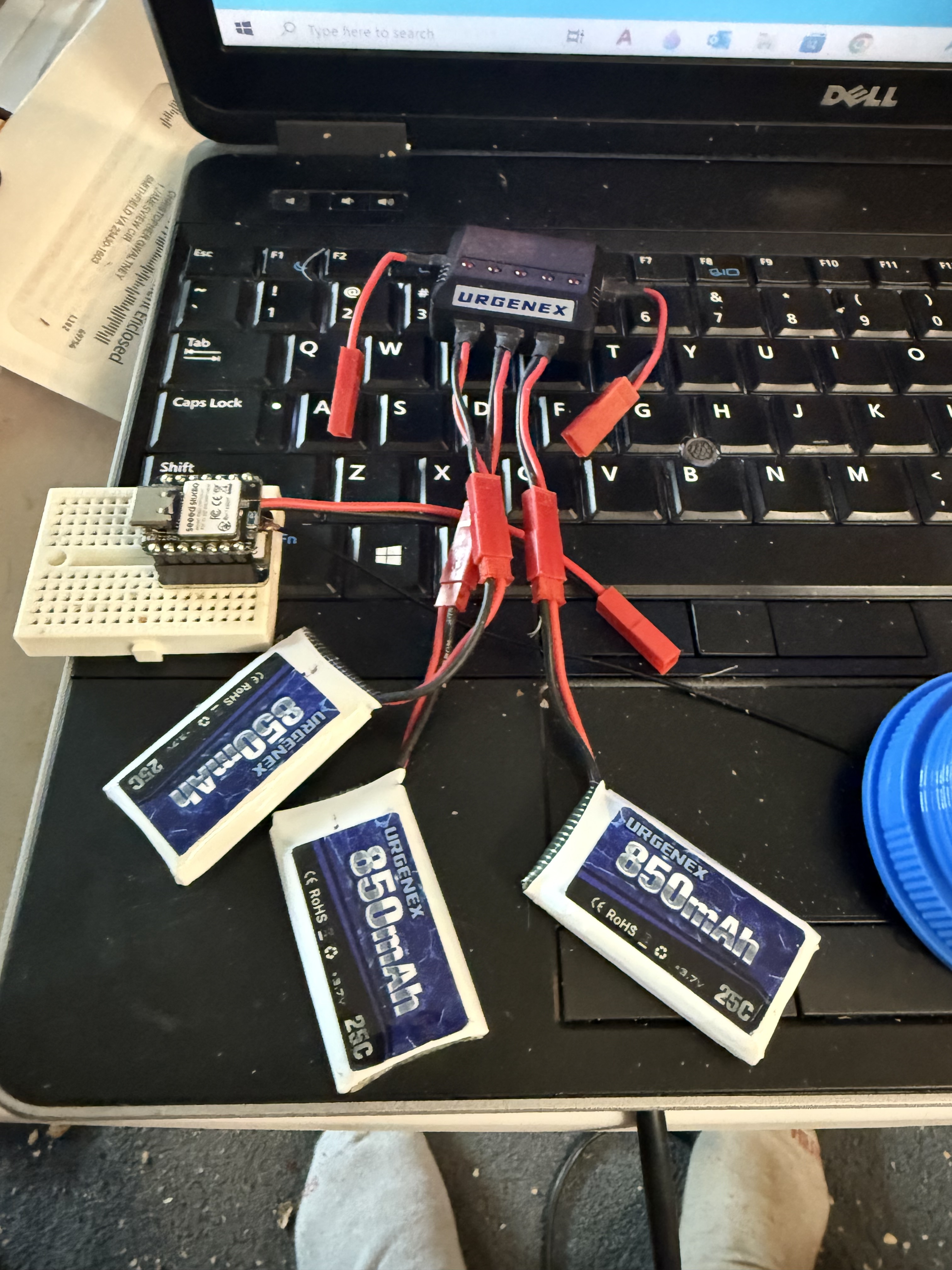
https://www.amazon.com/dp/B08T9FB56F
This is the kit i use to power all my XIAO Projects
will give about 2 days between charges for low power
but will drain quickly if you use alot of wifi or GPS unnecessarily
Hi there,
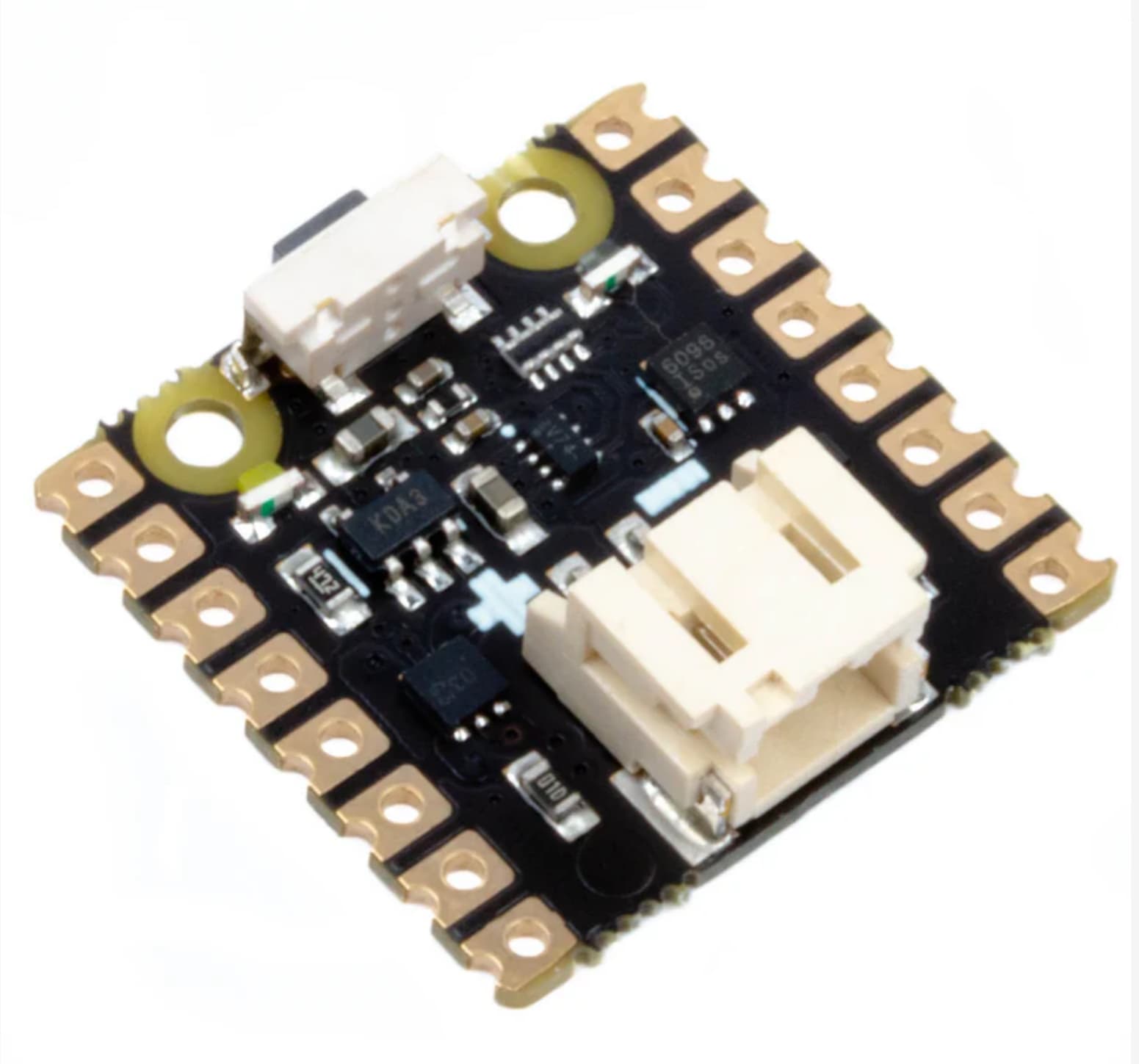
Yea, sure thing, you just need this section adjusted for a Xiao and use the Battery connection on the bottom of the board. combined with something like the second pic if you don’t like the other STyle the way they do it.
couple hours you could create the same but better for the Whole Xiao family, as the battery monitoring seems to be the achilles heel for seeed.  Thos ever moving bottom battery pads requires several model’s unfortunately
.
HTH
GL PJ
as you know the xiao already has a battery charger on it, I planed on leveraging that also. (no point in reinventing the wheel )
Thanks @cgwaltney and @PJ_Glasso for all your help and guidance!
I’ll be running simulations for now to test things out.
That said, I couldn’t quite figure out from the circuit how the push button is supposed to send a signal to the GPIO. If anyone has suggestions or insights, I’d really appreciate the input.
I am also exploring possibilities to add a separate slide switch for main power ON/OFF functionality. If anyone has recommendations or experience with similar setups, I’d love to hear your thoughts.
And once again, a big thank you to PJ for the continued support!
Hi there,
No worries , we are all here to help each other.
So let’s run it down a little, (I just don’t have enough time now , to EasyEDA one up or I would , because this is a VERY GOOD Idea and this is very needed besides it would be a fantastic enhancement to the XIAO accessory pool)
HELLO SEEED… Is this thing on 


you solder it on the bottom of the Xiao it makes connections with the battery pads to control the ON/OFF , The battery connects to it’s Bottom(JST) connector. You add it to the XIAO bottom like a sandwich,
( I had some pics of it mocked up, search)
The schematic above is incomplete of course it was just a starting point , the GPIO control could be added to U4(pin2) or Diode or’d with U5(pin 7) achieving the GPIO (hard shut down) IMO a better approach YMMV would be to sleep it and wake-it up, the RESET would not power it back up (you would need to press the button) but it would be cleaner maybe AFAIK. also some FETs for the battery charger passthrough. If done right and add a PMIC to the mix you still only need to connect the battery pads and the I2C pins to the Host Xiao. (much like the XIAO logger board accessory)
Giving it an ON/OFF power switch with GPIO (power off control)  100% Battery SOC assessment capabilities, extending the life and usefulness of ALL Xiao’s for pennies
Let’s face it the battery reading capability has been the achilles heal for XIAO , let’s fix that!
minor shade…warning. Don’t get me wrong, The voltage divider and Analog(in) read hocus-pocus  is better than Zero or nothing but put plainly it’s a patch by today’s standards Nothing less than a PMIC would be in order. We can do better. I have faith you’ll find the real-estate or a sandwich board
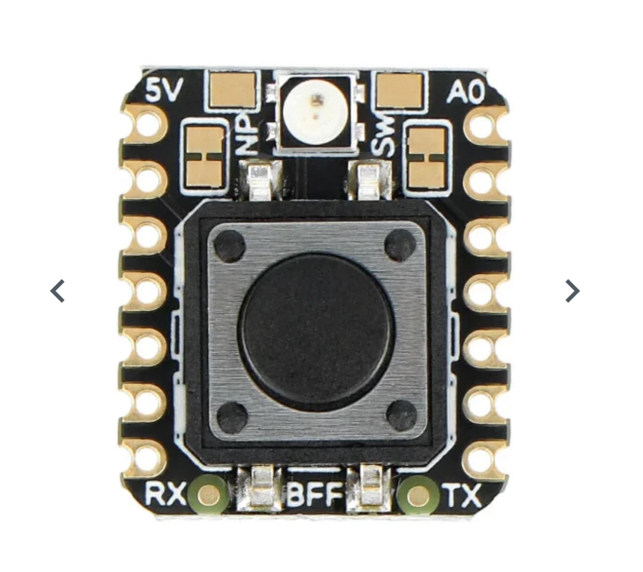
The second pic albeit confusing sorry I didn’t mean to conflate the two  is what a basic Xiao Big Button looks like (similar concept)
both are meant to be added to the bottom of the Xiao.
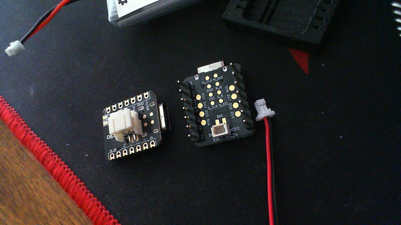
3rd pic was 2 ways to add a connector to a Xiao pads.
Hope that clears things up… it’s a lot to unpack but worthy of the discussion.
HTH
GL  PJ
PJ 
What does the big BFF button do? does it allow you to Phone A Friend?
LOL, can do…
What ever you want it to…
It was from the smallest one button BLE remote article. Button and a NeoPixel. pretty cool though none the less
GL PJ
Thanks much PJ for your elaboration. Makes things clear.
The below points definitely make sense in xiao ecosystem.
1.SOC(State of charge)
2.PMIC(Power Management IC)
I found the board you showed with button here Adafruit IoT Button with NeoPixel BFF Add-On for QT Py and Xiao : ID 5666 : Adafruit Industries, Unique & fun DIY electronics and kits
Good to know about it as well as a reference.
I will continue work on this further after all these inputs to see how it goes further.
Thanks for all the time and help always.
I have found that if I wire a switch between the EN pin under the board and ground, I can cut power to the board, while still allowing the battery to be charged.
Keeping the ESP32C6 in reset will draw some current. The OP wanted a complete (battery) isolation with a Push Button (momentary) to re-power.
Quite a straightforward task with a couple of mosfets and some R’s and C’s.