Edgebox-ESP-100 sample code compilation examples. (POWERED BY USERS)

Hi, I open this thread for put here all the samples codes that you have, and work for the Edgebox-ESP-100. Most in Arduino IDE but can work for other codes. I hope it helps everyone, if you have questions, comments or can support by sharing code and configuration we will all appreciate it.

“Pinout configuration with Arduino IDE”

  pinMode(DO0, OUTPUT);    // Set DO0 as an output
  pinMode(DO1, OUTPUT);    // Set DO1 as an output
  pinMode(DO2, OUTPUT);    // Set DO2 as an output
  pinMode(DO3, OUTPUT);    // Set DO3 as an output
  pinMode(DO4, OUTPUT);    // Set DO4 as an output
  pinMode(DO5, OUTPUT);    // Set DO5 as an output

 digitalWrite(DO0, LOW);  // Set DO0 low example for use it

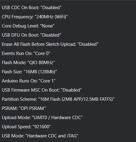
“LTE A7670G Initial Configuration”

--------------FOR VOID SETUP------------------------------

//Defining the Serial connection
#define SerialAT Serial2

void setup{

//Powering the LTE  
pinMode(16, OUTPUT);  
 digitalWrite(16, HIGH);

//Turn on the LTE
  pinMode(21, OUTPUT);  
  digitalWrite(21, HIGH);
  delay(1000);
  digitalWrite(21, LOW);

//Serial Config of LTE
  SerialAT.begin(115200,SERIAL_8N1,47,48);

//AT Configuration for connecting to a SIM operator, and work with SMS receiving data
SerialAT.println("AT+CFUN=1");  // Operacion FULL

  delay(1000);

  SerialAT.println("AT+CREG=1");  // registro de operador automatico

  delay(1000);

  SerialAT.println("AT+COPS=0");  // registro de operador automatico

  delay(1000);

  SerialAT.println("AT+CNMP=2");  // Uso de banda automatica

  delay(1000);

  SerialAT.println("AT+CMGF=1");  // sms modo texto desde incio

  delay(1000);

  //Borrar todos los sms

  SerialAT.println("AT+CNMI=1,2,0,0,0");  // modo de recibir sin guardar

  delay(1000);

  SerialAT.println("AT+CMGL=\"REC UNREAD\"");  // registro de operador automatico

  delay(1000);
}

--------EXAMPLE CODE OF WORK---------------------
//Study this code for SMS reception and control, change the variables or create it, for guide purpose

 void ALARMAS(){

  if(SerialAT.available()>0){

      // Serial buffer

      while(SerialAT.available()){

        incomingByte = SerialAT.read();

        buffer += incomingByte;

        }


        delay(10);

        buffer.toUpperCase(); // uppercase the message received

        Serial.print(buffer);

        //flagDel=1;

      }

    ///////////////////////LADO MOTOR ALARMAS///////////////////////////////////////////

      if(buffer.indexOf("CPDCLM1")>-1){ //LMFL = Fallo en lado motor de tornillo

        digitalWrite(DO0, HIGH);  // ROJO LADO MOTOR

        digitalWrite(DO2, HIGH);  // SEMAFORO Y SIRENA

        delay(1000);

        //flagDel=1;

      }

      if(buffer.indexOf("CPDCLM0")>-1){ //LMOK = Lado motor de tornillo OK

        digitalWrite(DO0, LOW);  // Set CH2 to low (0V)

        digitalWrite(DO2, LOW);  // Set CH2 to low (0V)

        delay(1000);

      }

    ///////////////////////LADO LIBRE ALARMAS///////////////////////////////////////////

      if(buffer.indexOf("CPDCLL1")>-1){ //LMFL = Fallo en lado motor de tornillo

        digitalWrite(DO1, HIGH);  // Set CH2 to low (0V)

        digitalWrite(DO2, HIGH);  // Set CH2 to low (0V)

        delay(1000);

        //flagDel=1;

      }

      if(buffer.indexOf("CPDCLL0")>-1){ //LMOK = Lado motor de tornillo OK

        digitalWrite(DO1, LOW);  // Set CH2 to low (0V)

        digitalWrite(DO2, LOW);  // Set CH2 to low (0V)

        delay(1000);

      }

    ///////////////////////SEMAFORO SOLO///////////////////////////////////////////

      if(buffer.indexOf("CPDCSM1")>-1){ //LMFL = Fallo en lado motor de tornillo

        digitalWrite(DO2, HIGH);  // Set CH2 to low (0V)

        delay(1000);

        //flagDel=1;

      }

      if(buffer.indexOf("CPDCSM0")>-1){ //LMOK = Lado motor de tornillo OK

        digitalWrite(DO2, LOW);  // Set CH2 to low (0V)

        delay(1000);

      }

    //////////////////////////////////////////////////////////////////////////////

      if(buffer.indexOf("+CREG: 3")>-1){ //VUELVE A TRATAR DE REGISTRAR CONEXION

        SerialAT.println("AT+CREG=1");

        delay(1000);

      }      

      if(buffer.indexOf("+CREG: 2")>-1){ //VUELVE A TRATAR DE REGISTRAR CONEXION

        SerialAT.println("AT+CREG=1");

        delay(1000);

      }

      if(buffer.indexOf("+CMS ERROR: 500")>-1){ //EN CASO DE ERROR 500 (SIM FUERA) PARPADEA,   OCUPA SIM Y REINICIO

        digitalWrite(DO0, HIGH);  // Set CH2 to low (0V)

        digitalWrite(DO1, HIGH);

        delay(1000);

        digitalWrite(DO0, LOW);  // Set CH2 to low (0V)

        digitalWrite(DO1, LOW);

        delay(1000);

        digitalWrite(DO0, HIGH);  // Set CH2 to low (0V)

        digitalWrite(DO1, HIGH);

        delay(1000);

        digitalWrite(DO0, LOW);  // Set CH2 to low (0V)

        digitalWrite(DO1, LOW);

        delay(1000);

        digitalWrite(DO0, HIGH);  // Set CH2 to low (0V)

        digitalWrite(DO1, HIGH);

        delay(1000);

        digitalWrite(DO0, LOW);  // Set CH2 to low (0V)

        digitalWrite(DO1, LOW);

        delay(1000);

      }

  buffer=""; //Limpia el buffer para evitar ciclado de ram

 }

“Arduino IDE functional configuration”

This configuration is very stable, keep running the watchdog in the cpu0 and uses the complete RAM, and flash.

EDGEBOX-ESP-100 ArduinoIDE most functional config

“Analog read of 4-20mA”

This example uses the Adafruit_ADS1X15.h library. and use an basic example for range process variable

#include <Adafruit_ADS1X15.h>
Adafruit_ADS1015 ads;     /* Use this for the 12-bit version */

uint16_t lectura; //stores always in uint16 for complete resolution
//if you stores in int16 or float, takes one bit for the sign, and first we need to handle the reading

void setup(void)
{
  Serial.begin(9600);
  Serial.println("Hello!");

  Serial.println("Getting single-ended readings from AIN0..3");
  Serial.println("ADC Range: +/- 6.144V (1 bit = 3mV/ADS1015, 0.1875mV/ADS1115)");

  if (!ads.begin()) {
    Serial.println("Failed to initialize ADS.");
    while (1);
  }
}

void loop(void)
{

lectura = ads.readADC_SingleEnded(0);

float Process_mA=(map(lectura,0,65535,4000,20000))/1000; //for obtain the 4-20mA 

//Example for variable ranging, in temperature 0 to 400°C
//Pv=[(Pv high-Pv low)/(I high-I low)]*(I-I low)+Pv low

float Temperature=(((400.000-0.000)/(20.000-4.000))*(Process_mA-4.000)+1.400); 
// the last 1.400 is a gain for error in readings, you may need a temperature reference patron to adding, so the 1.400 can be deleted


}


“MODBUS RTU Slave”

This example show the Slave mode of modbus, using the library of emelianov (is the best library that i found, most complete and working, tested on industrial field). Maybe the sintax or the order of code can be changed or improved, so play with that.

Copyright (C) 2019-2022 Alexander Emelianov (a.m.emelianov@gmail.com)
GitHub - emelianov/modbus-esp8266: Most complete Modbus library for Arduino. A library that allows your Arduino board to communicate via Modbus protocol, acting as a master, slave or both. Supports network transport (Modbus TCP) and Serial line/RS-485 (Modbus RTU). Supports Modbus TCP Security for ESP8266/ESP32.

#include <ModbusRTU.h>

#define RXPIN GPIO_NUM_18
#define TXPIN GPIO_NUM_17
#define REDEPIN GPIO_NUM_8
#define SLAVE_ID 10
ModbusRTU mb;

uint16_t p1,p2;

void setup() {
   
   pinMode(DI0,INPUT);
   pinMode(DO0,OUTPUT);
   Serial1.begin(19200,SERIAL_8E1,RXPIN,TXPIN);
   mb.begin(&Serial1,REDEPIN);
   mb.slave(SLAVE_ID);
   
}

void loop() {

    mb.addHreg(0); //Add Hold register 0          
    mb.Hreg(0,p1); // 40003 for PLC base 1 4x, only uint16 data (p1 and p2 are uint16 variables) when the master receive can change to signed 
    mb.addHreg(1); //Add Hold register 1 
    mb.Hreg(1,p2); // 40003 for PLC base 1 4x, only uint16 data  

    mb.addCoil(0,0,10); // Add 10 coils 0 to 10 with 0 value
    mb.Coil(0,digitalRead(DI0)); // The input DI0 writes the coil 0 in the modbus protocl
    digitalWrite(DO0,mb.Coil(5)); //The output DO0 was written by the coil 5 in the modbus protocol
    mb.task(); //tasking of modbus
    yield();  //logistics of modbus

    //Pv=[(Pv high-Pv low)/(I high-I low)]*(I-I low)+Pv low
    float Pressure=    (((10.000-0.000)/(20.000-4.000))*(Process_mA-4.000)+0.000);
    //Process_mA is from analog read example LOOK OUT
    p1=Pressure*100; //Split the integers to send it on uint16 for the modbus
    p2=Pressure/100; //Split the decimals to send it on uint16 for the modbus

}