Does anyone have any tips for usage of the programming port… not sure how I can solder wires or a header with this yellow thing in the way without removing it. Not sure it’s a good idea to let pins just sit in there unsecured either.
Bump. This is not feasible…
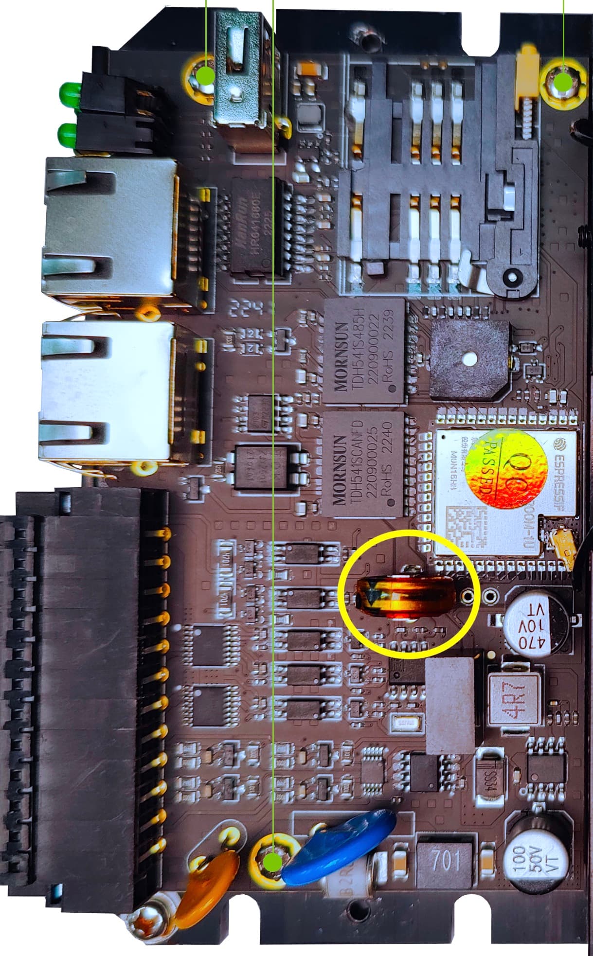
Take off the 3 screws (marked in green in the picture) and flip the board over. It’s very frustrating that there isn’t a standard usb programming port!
That’s what I’ve done - but the issue is you are either letting wires rest in the holes unsecured, which would risk touching things they shouldn’t. Ideally I could solder some header pins - but to do that i would need access to the pins from the other side, which I can’t do without removing the supercap. If I wanted to deploy 1000 of these devices it’s simply not feasible to do that.
If your otherwise excellent product is to have a chance of being used for something serious, then a solution must be found on how to easily upload firmware.
It does not make sense to take it apart and solder the wires yourself.
We will use them in batches of 25 to 50 - it will take several days to program them ![]() .
.
1 Like
I solder on from the back with a jumper by tinning the wire and tacking it on - it doesn’t have to be perfect to quickly upload. Just be careful with handling the wires. I have a dev box I use that I leave some jumpers coming out of a hole I drilled, and for prod versions I do OTA updates so you only have to do it once.
We also plan to use in batches of 8-16, so yeah it’s a lot of work for the initial programming. What an unfortunate design choice for an otherwise great product.
Wow, this is a dealbreaker
I removed the screws then made a programming cable using a USB to TTL Serial 3.3V Adapter Cable TX RX, GND solder to Connector Header Through Hole 4 position 0.100" (2.54mm). Then push it into the board holes no solder needed. The cable is used one time, OTA updates not internet.
Hi.
I adapt very basic module for programming the Edgebox-ESP-100, i solder inside a Ftdi Ft232rl usb and the GPI0 is bridged with a terminal to gnd, later i opened a space to get the usb port out. This is the first edgebox that modify.
Is not the best good looking for the first, but in this way for programming, is not necessary open the box and the bridge is only a SW_NO with retention, or a din terminal blade.
By the way, you can use or develop some more with the Ftdi Ft232rl for not using this unconventional solution, i put the link of i use, and i hope this helps:
https://www.reddit.com/r/esp32/comments/hn46cx/a_usb_dongle_to_control_en_and_gpio0_directly/
I soldered four male headers to the programming port. Here is what I did. I hope it helps.
The four headers I soldered were attached (not four individual headers). That helped because the pitch of the programming slots is larger than the standard 2.54 mm pitch. You have to work the headers in (stretch the outer two a little) but this creates a little tension on the pins after you insert them, which keeps them secure while you solder. You basically gain an extra pair of hands.
With the pins in place, you can solder three of the four (not the one under the cap). I used thin solder and came in with the solder from the side. Iron from other side.
Last pin. On the male header side (and on the side away from the other three pins) I cut the insulation of the pin to expose the metal of the pin. And that is what I solder to the board. Is it a little kluge? Yes. However, it worked for me. I’ve yet to put case back together. Not sure if this will cause a problem with reassembly. One issue at a time.
Regards, Mark