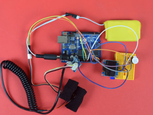
Hello. In 2019, I made this circuit using Seedstudio’s Grove-GSR sensor. I named it ‘Discomfort Alert’. This circuit measured the output of the sensor and showed it in the OLED display. When the output value crossed a threshold value, the buzzer made a sound. It made a sound when the person wearing the sensor needed to pee. I did this project keeping disabled patients and baby patients in my mind. The project was very close to my heart. The concept came when my only son who was 2.5 yr old that time was suffering from dengue. He was admitted in a hospital and the docs always told me to keep a record of his urine output. After coming back to my office from leave , I started this project.
Here is the code I used.
#include <SPI.h>
#include <Wire.h>
#include <Adafruit_GFX.h>
#include <Adafruit_SSD1306.h>
Adafruit_SSD1306 display;
const int BUZZER=3;
const int GSR=A0;
int threshold=0;
int sensorValue;
void setup(){
 long sum=0;
 Serial.begin(9600);
 pinMode(BUZZER,OUTPUT);
 digitalWrite(BUZZER,LOW);

 delay(1000);
 for(int i=0;i<500;i++)
 {
 sensorValue=analogRead(GSR);
 sum += sensorValue;
 delay(5);

 }
 threshold = sum/500;

 Serial.print("threshold =");
 Serial.println(threshold);
}
void loop(){
 int temp;
 sensorValue=analogRead(GSR);

display.begin(SSD1306_SWITCHCAPVCC, 0x3C);

  // Clear the buffer.
 display.clearDisplay();
 display.display();

 display.setTextSize(1);
 display.setTextColor(WHITE);
 display.setCursor(0,0);
 display.print("Threshold =");
 display.println(threshold);
 display.print("sensorValue =");
 display.print(sensorValue);
 display.display();
 display.clearDisplay();
 Serial.print("sensorValue=");
 Serial.println(sensorValue);
 Serial.print(",");
 Serial.print("Threshold=");
 Serial.println(threshold);

 temp = threshold - sensorValue;
if(abs(temp)>80)
 {
 sensorValue=analogRead(GSR);
 temp = threshold - sensorValue;
 if(abs(temp)>80){
 digitalWrite(BUZZER,HIGH);
 Serial.println("Go to toilet");
 delay(3000);
 digitalWrite(BUZZER,LOW);
 delay(1000);}
 }
}
I want suggestions to make the project usable in practical life. Yes, I wore it and tested my circuit but this arrangement is not useable for a real disabled person in real life. Another thing I noticed was, the threshold value could be different for different people in different environment. It looked like, I had to set the threshold value after testing on the individual who was going to wear it.
Any suggestion for the betterment of this project is welcome.
Love,
Barsha
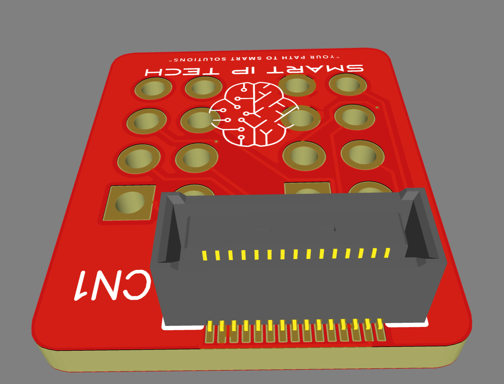
I am also thinking about replacing the breadboard with a custom PCB. That would make the device smaller and more reliable. I am considering using Card edge connectors to simplify module connections and improve the overall design. Do you think this is a good approach? Are there better connector options for a small wearable device?
Hi there,
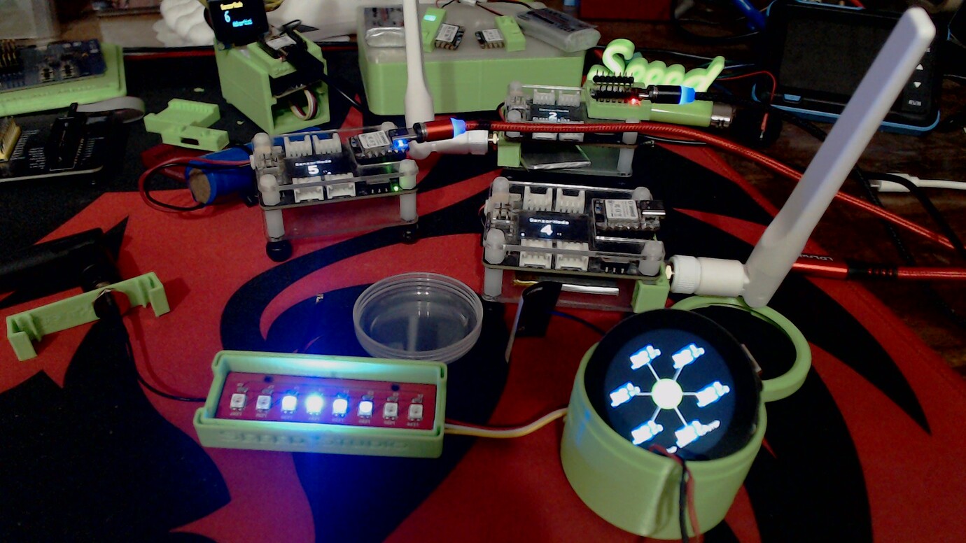
So, looking and lurking on this, The Round display comes to mind, I.E. a " Pendant "
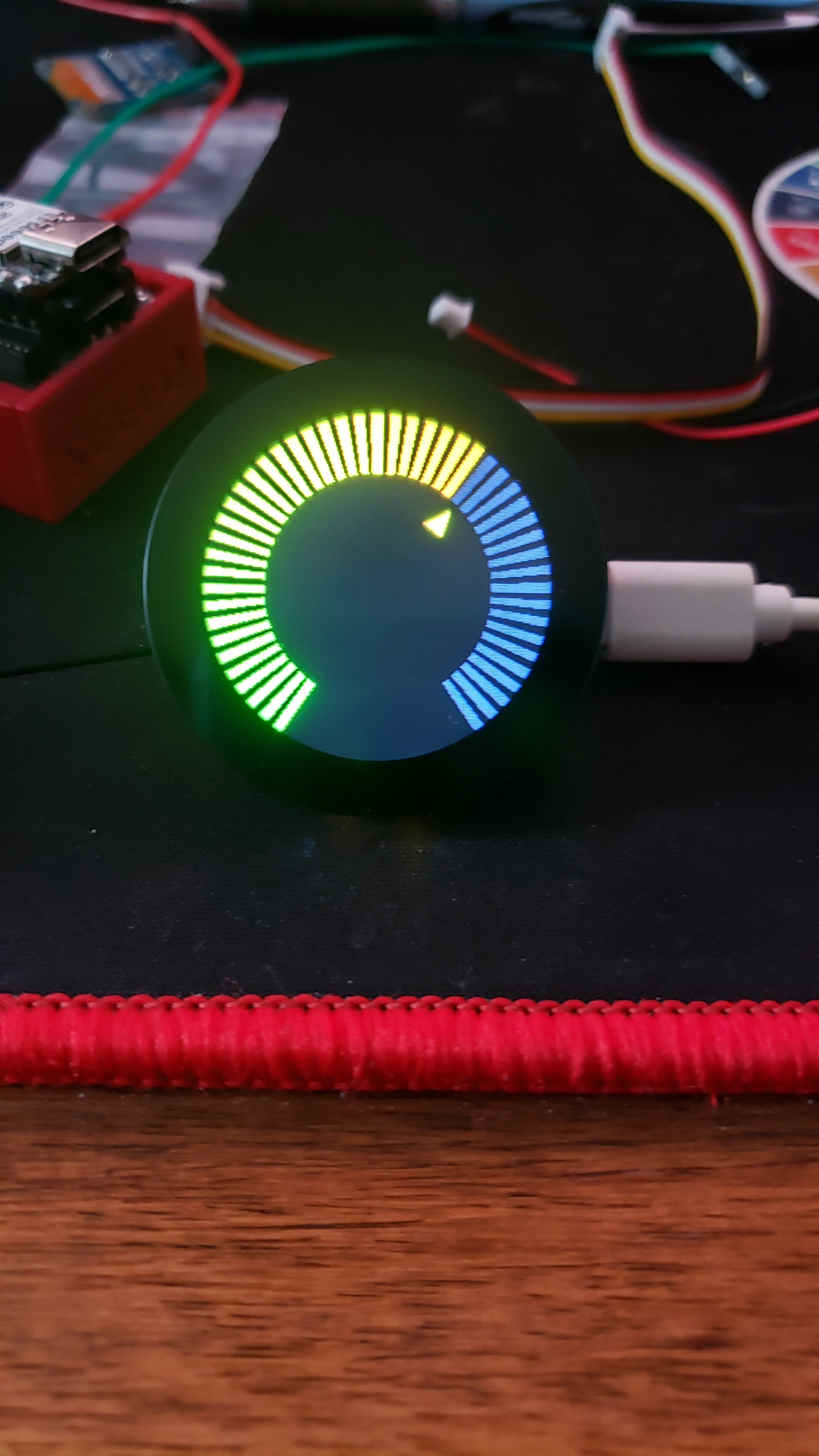
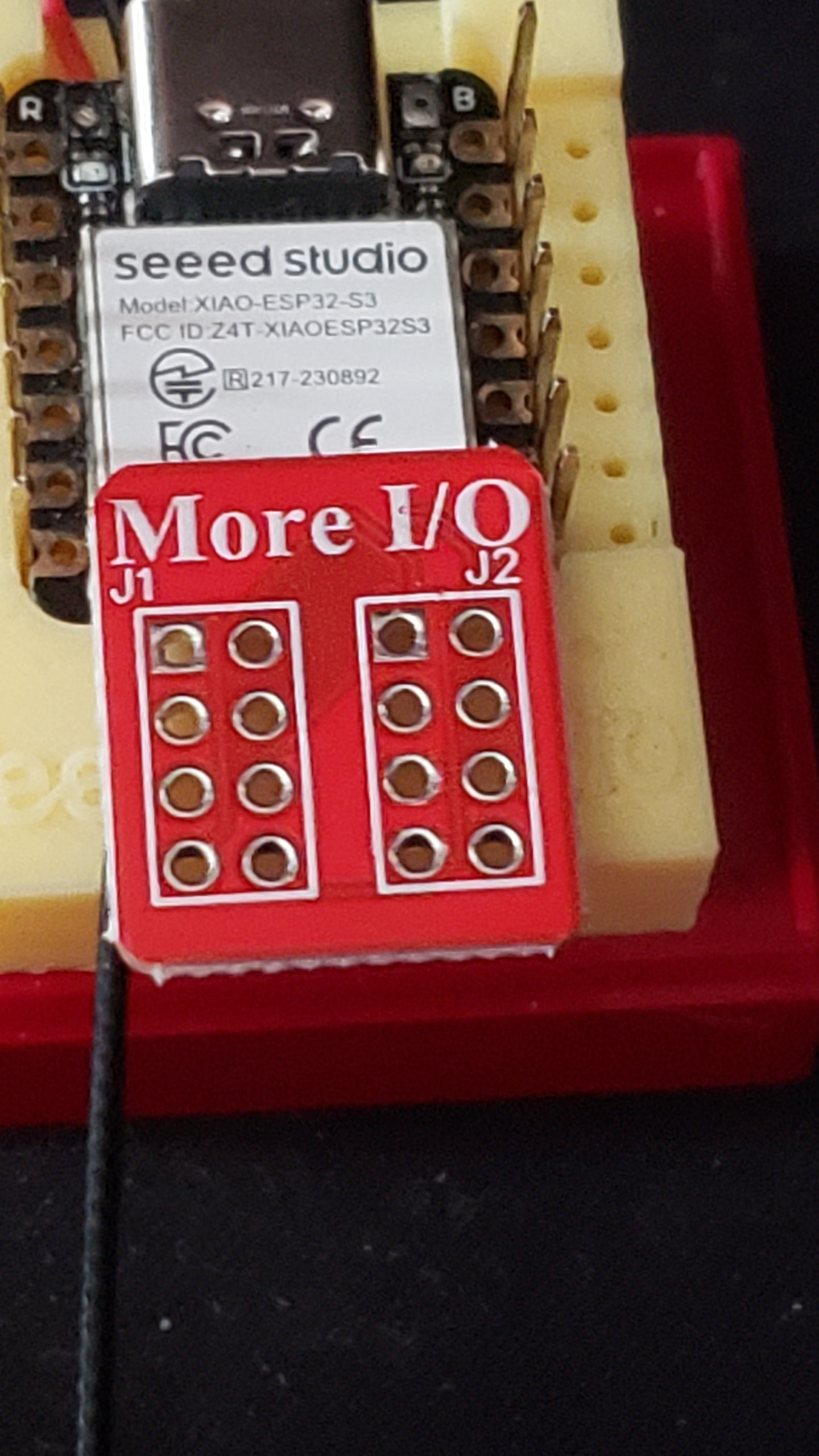
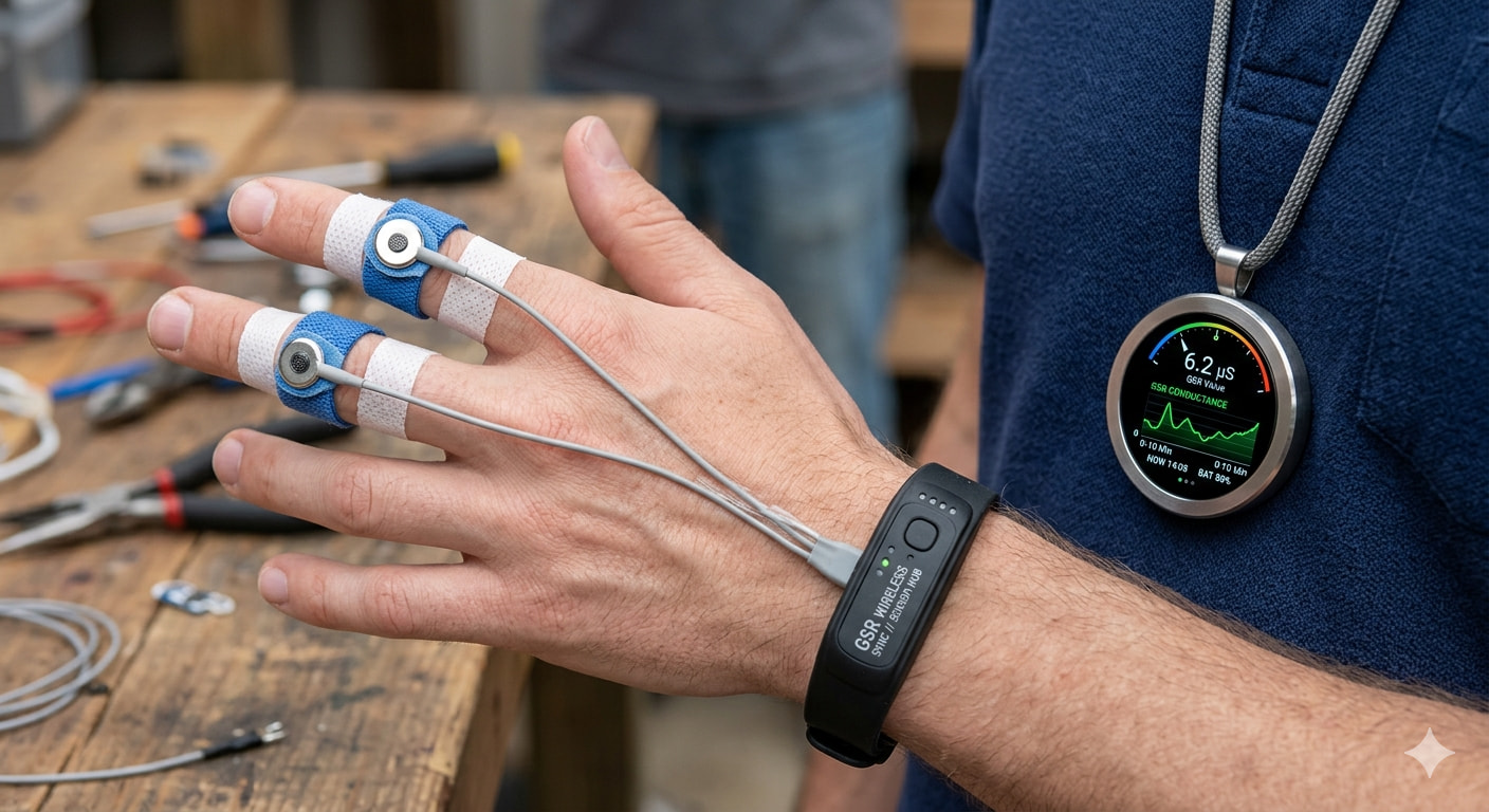
Make the Round display on a long chain , the size of the Round container can be scaled for different battery sizes all round of course, add the Grove More I/O board for the GSR sensor connection. (calibrate for the length of the cable for signal level) add offsets via BLE or touch screen dial controls, like m\y demos on round display.
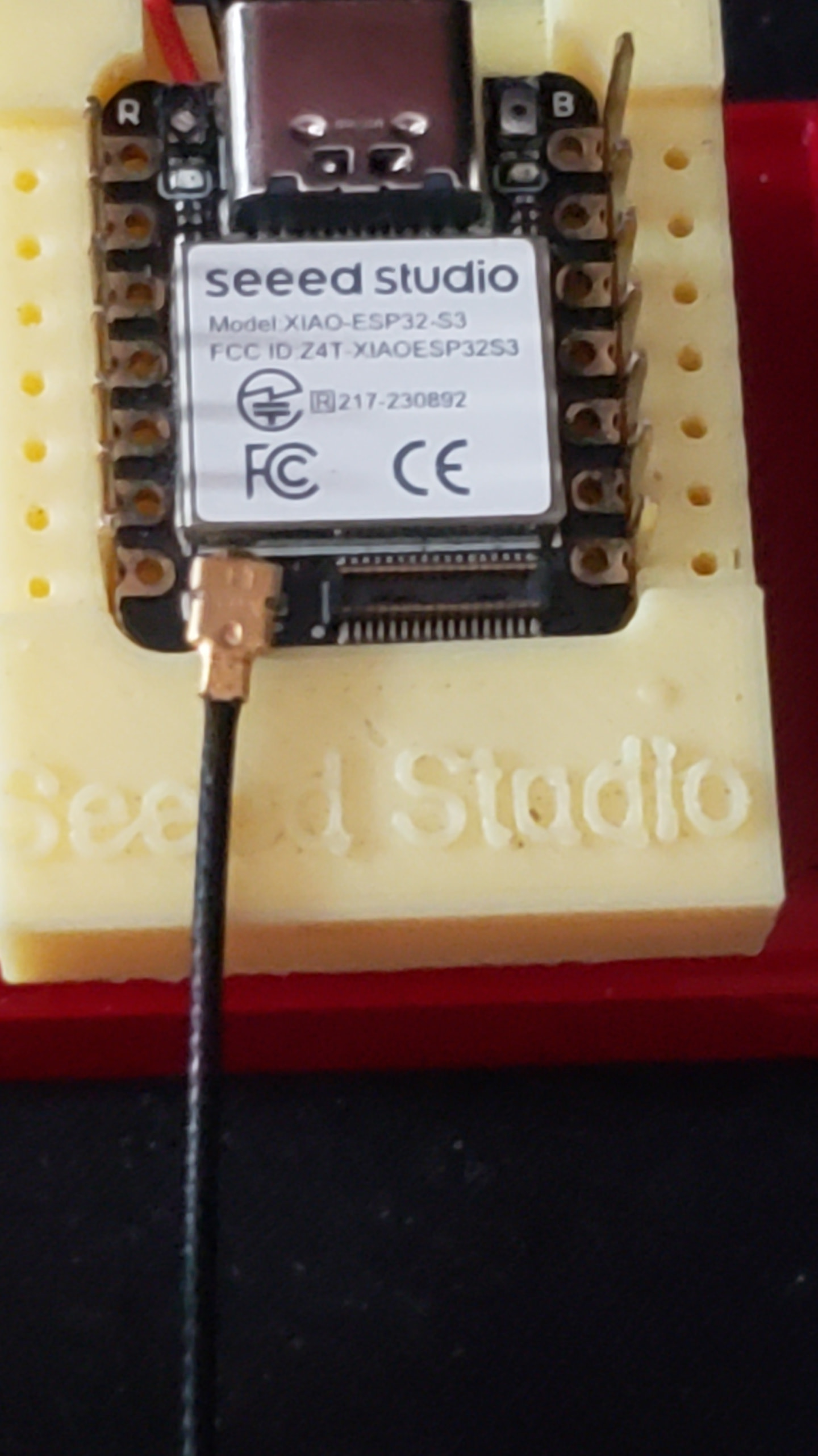
USE a Esp32S3 with the B2B connector and make what ever custom adapter you might need. B2B to Anything…
Besides the built in SD for recording, or use a Nrf52840 Sense Plus part and add “orientation” & Fall or Motion" to the mix with the IMU, You can Mirror the device controls with you mobile phone over BLE and get status , battery , alert and notifications.
You got a good foundation , just update it to current tech and gain a lot of extra abilities to improve overall reliability size and function.
HTH
GL  PJ
PJ 
Thank you sir. My main headache is making the setup wearable and compact. Groove- GSR sensor electrodes must be worn in index and middle fingers. But the GSR sensor board isn’t wearable. This is where the problem starts.
Hi there,
SO it is open source and the schematic is available, I faced a similar situ with the Grove EGC unit board. I used the schematic and created a 3 channel board just by cut and paste. Make it wearable, Get the schematic, re-layout the current board and change the connectors, add a B2B and it would snap onto the round display’s esp32S3 (connection to xiao eliminates the need for the grove connector) then replace the Bulky cable to sensor band/cuffs/pads? it does, not need to be so heavy or long , change the Pendant to a wrist watch band type design, but wide instead of Tall.
Bottom line is how are your Technical Knowledge chops?
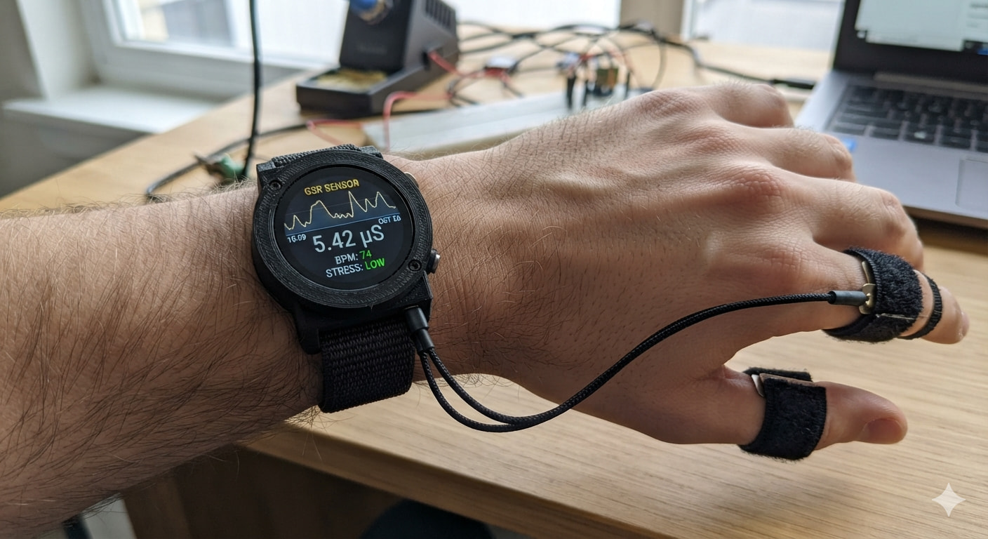
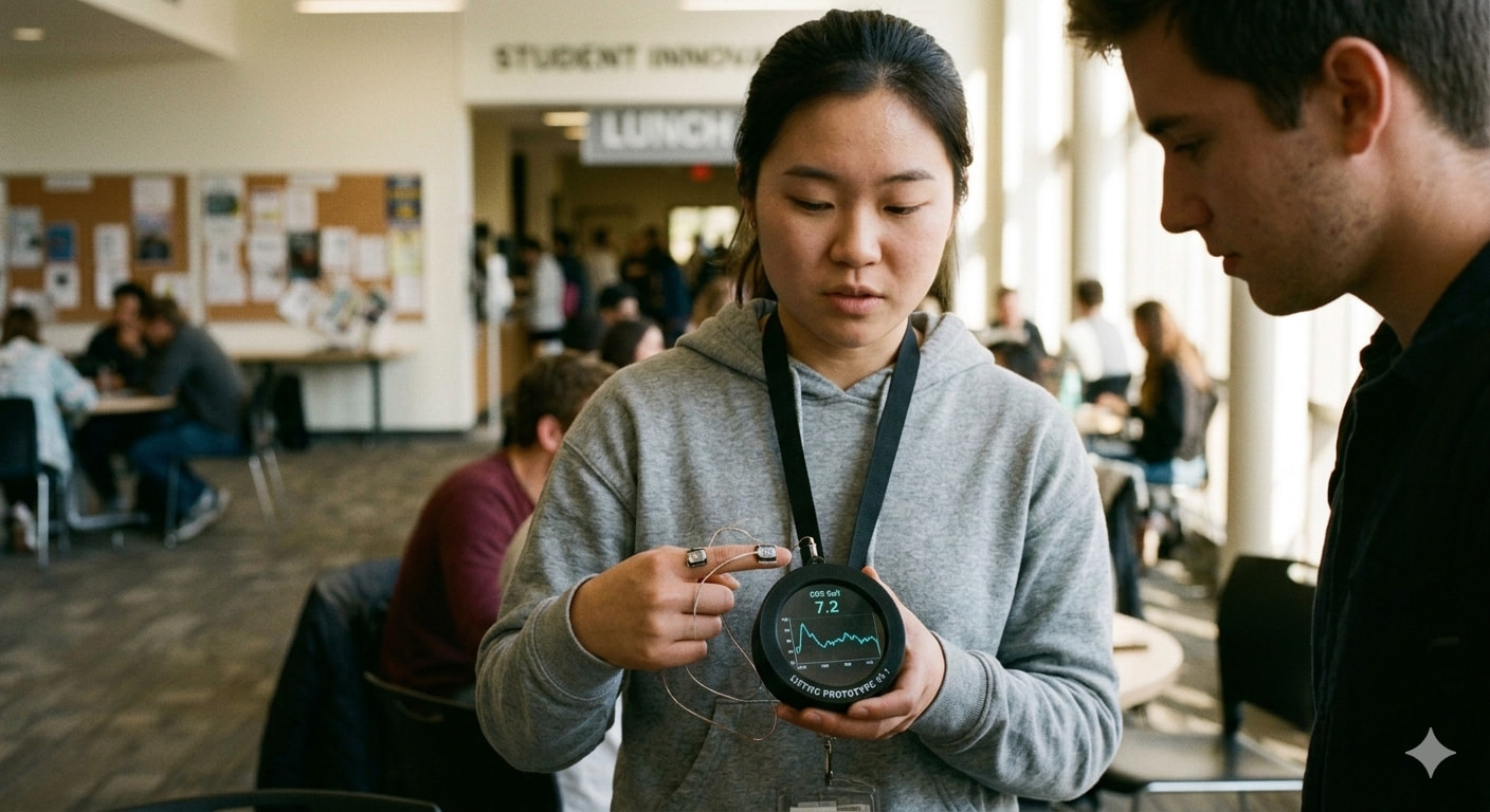
seems , AI can envision what I’m discribing..  WILD
WILD 
Welcome to level 2
HTH
GL PJ
It’s a very worthy project , stretch your skills and make it happen.
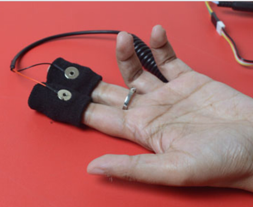
Sir, seeing the picture you posted, I have one question in my mind. shouldn’t the electrodes be worn on the tip of the fingers like this?
Hi there,
LOL,
That is " AI " for You…
The other render had a BP cuff around the dudes Neck.. 
this was what it gave me back from a prompt for a render of a round display
"
Can you render a picture of a watch like worn display with set of short leads as a GSR sensor for tweo fingers. I use the Seeed Studio Round display.
Even there is no such thing as “tweo” fingers, either…
My point was “this” is how I would build it, and have done similar.
customize the platform to fit your design criteria..
Just in the other Tab I described wrist worn wireless version and pendant instead , SO you see it is ALL possible.
I like this Flav-O-Flav version too.
HTH
GL PJ
stay motavated.