Hello.
I need help with connecting a set of devices.
Xiao esp32s3 plus, wio sx1262, powered by a lipo directly.
The controller with the lora module connected via the standard connector needs to be connected to:
- 5 micro servo feetech ft109b - D11, D12, D13, D14, D15, powered by an external lipo through a flywoo 04 1s bec 5V 3A boost module.
- i2c accelerometer and barometer sensor GY-91 - D17, D18, powered by 3.3V xiao.
- GPS beitian BE-122 - D6, D7, powered externally from lipo via flywoo 04 1s bec 5V 3A boost module.
- 1 LED - D19, powered by xiao pin
- 2 buttons - D16, D0
There are low-ESR and ceramic capacitors for the servos, resistors for the buttons and LED, and filter capacitors for the GPS and gy-91 in the circuit.
The power is supplied from a single lipo through a mosfet, so that when the xiao is connected to the USB, the power to all devices is turned off.
Question:
Are the pins on the xiao selected correctly for the devices?
Will there be any conflicts?
If I have made a mistake, please correct me.
D0 is a boot pin, remove it. D16 button is fine. D17/D18 I2C may work but not ideal. Use safer I2C pins like D4/D5. D11–D15 servo pins are OK. GPS D6/D7 may work, verify UART mapping.
LED on D19 is acceptable. Main risk: power noise and servo resets.
Thanks. I couldn’t figure out how to connect the wio sx1262, and what pins it takes from the xiao esp32s3 plus. If I move the i2c to D4 D5 and both buttons to D1 D2, will it interfere with the radio module?
Hi there,
You may want to consult the Technical specification guide , and or the pins sheet in the wiki, LOOK at what power domains the pins you choose to use on a particular interface , CS or GPIO pins should ALL belong to the same group to start, there aare caveats, so consult the doc’s 
HTH
GL  PJ
PJ 
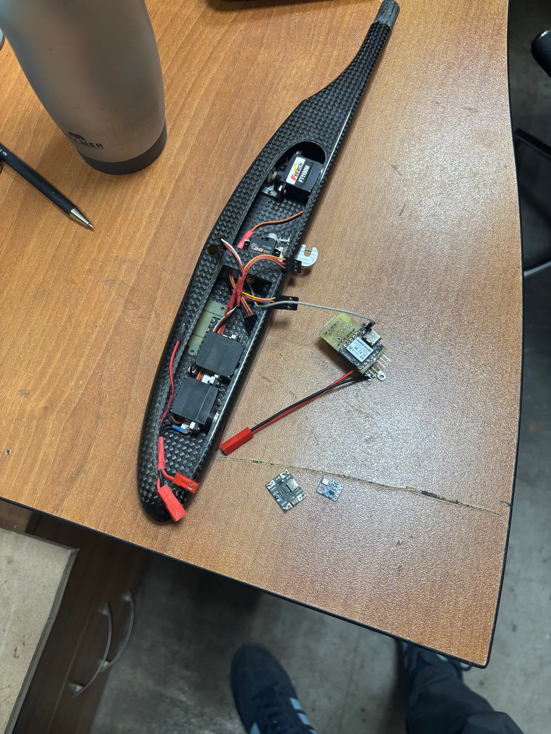
I tried to figure it out, and it turned out like the picture attached. Please check it out. I’m not an expert in electronics or programming, but the result is extremely important to me. This is a project for an electronic timer for a free-flying F1A model.
Will this work? Am I doing it right?
Hi there,
So lets see How the image analyzer see’s it ?
I fed it in and got this reply, now im LOL…
AI=ON…

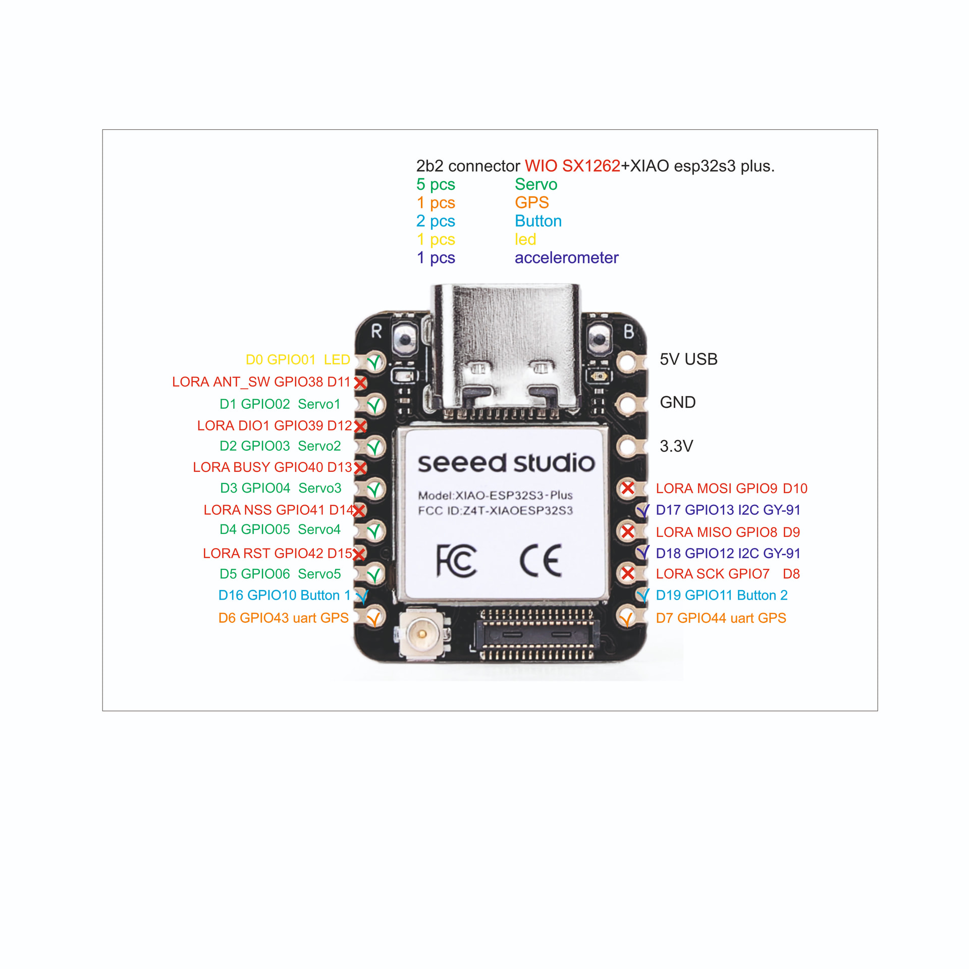
Based on the schematic in the Seeed Studio Forum post, the user is attempting to map several peripherals (Servos, GPS, LoRa, Buttons, I2C) to the XIAO ESP32S3 Plus.
Power Domain & Pin Analysis
The XIAO ESP32S3 generally operates on a 3.3V logic level. When using high-power components like servos alongside sensitive communication (I2C/LoRa), the “Power Domain” refers to ensuring that high-current draw from servos doesn’t cause voltage drops (brownouts) on the pins used for data.
According to the diagram and the advice from community regulars like PJ_Glasso, here is the breakdown of the pin assignments:
| Function |
Pins Used in Image |
Status / Correctness |
| Servos (5x) |
D1, D2, D3, D4, D5 |
Correct. These are standard GPIOs. However, servos should be powered by the 5V pin, not 3.3V, to avoid crashing the MCU. |
| GPS (UART) |
D6 (TX), D7 (RX) |
Correct. These pins support UART mapping. Ensure the GPS module logic is 3.3V compatible. |
| I2C (Accel/Display) |
D17, D18 |
Caution. On the XIAO ESP32S3, the “Standard” I2C pins are usually D4 (SDA) and D5 (SCL). Moving them to D17/D18 is possible via software mapping, but may conflict with internal flash/PSRAM domains if not careful. |
| Buttons |
D16, D19 |
Correct. These are general-purpose pins. D16 is often preferred as it is a “safe” boot pin. |
| LoRa (SPI) |
D8, D9, D10, D11-D15 |
Critical. The LoRa module (Wio SX1262) uses the SPI bus. You must ensure the CS (Chip Select) and Reset pins do not overlap with the Servo pins (D1-D5). |
Key Risks Identified in the Picture:
- I2C Conflict: The user has moved I2C to D17/D18. While the ESP32S3 is flexible, the community member loveforcircuits suggests moving I2C back to D4/D5 for better stability, as these are the native hardware I2C pins.
- Servo Power Noise: This is the biggest “Power Domain” risk. If the 5 servos move simultaneously, they can create electrical noise that resets the ESP32S3. It is recommended to add a large capacitor (e.g., 470µF) across the GND and 5V rails.
- Boot Pins: Using D0 (GPIO1) for an LED as shown is generally safe, but if D0 is pulled LOW during a reboot, it can force the chip into a different boot mode.
Recommendation
If you are following this project, the most stable configuration for the XIAO ESP32S3 is to keep the I2C on D4/D5 and move the servos to other available digital pins, ensuring the LoRa SPI pins (D8-D10) remain dedicated to the radio communication to avoid interference.
Are you building this specific F1A glider timer, or just verifying the pinout for a similar multi-device project?
"
Mind you all that from just the image… and this prompt..
here is a new one, it is about using the correct pins in the same power domain, can you tell from this picture? which pins are correct for the function the user wants to use them for./
https://forum.seeedstudio.com/uploads/default/optimized/3X/4/a/4a01e55817c566697c1c7a4fe6c2eb6ab51da4ab_2_1000x1000.jpeg
HTH
GL PJ
Hello. Thank you! I will definitely take your recommendations into account.
The configuration will be as follows:
Servos (5x) - D1, D2, D3, D17, D18.
GPS UART - D6, D7.
Accelerometer i2c - D4, D5.
Buttons - D16, D19.
LED - D0.
I have already assembled such a timer on xiao nrf52840, it has an accelerometer, but there is no ready-made wifi, and for some reason the servos on nrf52840 are shaking, but on esp32 they work perfectly. Now there is a need to send data from the device about the location to search for a model, so the lora module is important here. I have already considered all the power recommendations, low ESR capacitors and ceramics, external button resistors, ceramics capacitors on the sensor and Gps power lines, and I have considered everything. I will test it, I hope there will be no problems with the pinout. Thank you for your help!
Hi Konstantin,
The nrf52840 actualy has better pwm resolution than esp32. You need to use hardware PWM library in order for the signal to be stable. And nrf52840 is more energy eficiant.
Best luck
Interesting project keep us posted
Hello. I know about energy efficiency, but I couldn’t get everything to work properly, and the servos were jerking. However, they worked well on the esp32. In my image, the lora pins are displayed correctly, but I moved the i2c to the standard d4 and d5 pins, and the servos were placed in their place. Everything works as expected. I generally like the xiao esp32s3 plus, but I strongly miss the built-in 2.4 GHz WiFi antenna. It’s surprising that the manufacturer only included an ipex connector.
I have made a F1A timer with both Xiao nrf52840 and Esp 32-c3 boards. Thay both are working.
I have also made a independet GPS tracker with RDT using ebyte e-220 modules. I have shared the GPS so anyone can use it. Just find the group DIY - F1A gliders, you can find it there.
Здравствуйте. Пришлите ссылку пожалуйста
Sorry, the forum does not allow shearing lings. Look for me on Facebook, Vasil Calev