Basically i am building project where i am using every analog pins possible on the classic Xiao ESP32-S3 which means that i actually need one of the two pins on the shield to do analog readings for a potentiometer.
However i have been met with the issue that i cant seem to get any of those pins to do any analog readings.
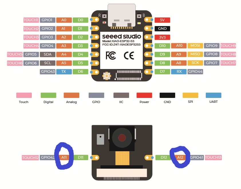
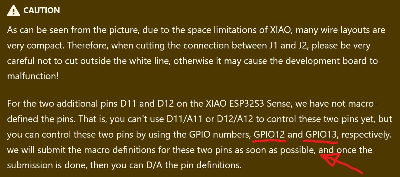
First of all on this page : Pin Multiplexing with Seeed Studio XIAO ESP32S3 (Sense) | Seeed Studio Wiki , it is suggested that these pins are capable of analog readings but that you need to access them using their GPIO names as opposed to their macros (such as A11 and A12).
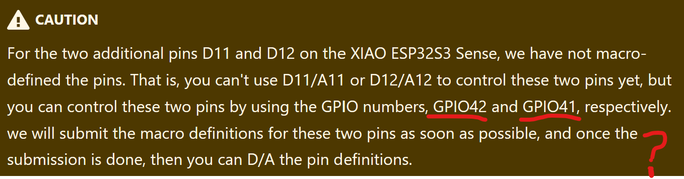
The first confusing thing is that this page gives opposite indications on those GPIO names, check out the yellow boxed text in the step 1 and step 3 of the “For Sense” section. One of them tells to use GPIO 12 and 13 and the other 42 and 41 :
Anyway after testing and using any of those GPIO, i wasn’t able to get any analog readings from those pins, also note that i did cut the traces on J1 and J2 as indicated in the wiki.
Could anyone help me understand this issue?
Thanks you for reading !
do you understand what they mean macro-defined the pins?
that means in Arduino IDE you have to use the correct BSP Board Support Package the BSP defines macro DEFINE STATEMENTS in arduino IDE that allows you to use A11 as a variable representing the actual GPIO pin number… this is not obvious how this works in the background under the hood. If the DEFINE statements are not properly defined the use of (A11) in the code will not work… dependingo on your code you will have to manually enter the pin numder into the code, not as a variable but as a literal (42) not even GPIO42) HOPE THAT HELPS…
Hello, yes i did use the single 41 and 42 numbers for the GPIO in an analogRead(), however it is still not working.
I don’t understand why those pins would be be advertised as analog if they aren’t capable of doing that.
Has anyone ever managed to get an analog reading out of those two so called “analog pins” on the Sense shield ?
If so i am really curious how…
i am for sure they must be analog capable because they go to the microphone… maybe you are not activating the pins correctly… look dor icrophone code… you didnt say exactly how you think they are not working
In platformIO, i can use the 41 and 42 GPIOs in digital write, digital read but not in analog read mode, when i try to do, here is what pops up in my serial read :
[E][esp32-hal-adc.c:267] __analogRead(): Pin 41 is not ADC pin!
Check the datasheet or reference manual to see what pins are ADC capable.
GPIO 41 or 42 don’t seem to be…
Also some ADC pins can’t be used when WiFi, Touch or UART1 is used.
This might be the answer you’re looking for: By default in the factory state, the D11 and D12 pins on the Sense shield are connected to the microphone. So if you need to free up these two pins for other uses, you’ll first need to cut the J1 and J2 pads. Be very careful when cutting—avoid damaging other circuit traces or injuring yourself.