The LED does not turn on. I tested it with a normal sketch with no interrupts and it works.
So it is not a hardware issue. The LED and the button work.
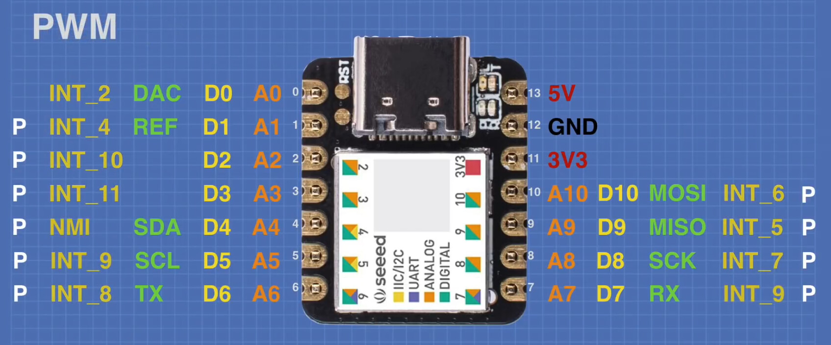
I saw a video by Dronebotworkshop, were I got this pin diagram
This makes sense if Start_BUTTON_pin is the pin connected to the button … I had assumed, that the pin you wanted to monitor was Start_BUTTON_INTpin.
What is that pin connected to?
Also, you should probably do something like this (just to get into the good habit of not doing too much in your interrupt routine.
void loop()
{
  // This will make sure you are not interrupted whilst reading the *volatile*
  // variable remember that ISRs have a higher priority than loop()
  __disable_irq();
  bool triggered = Start_BUTTON_triggered;
  Start_BUTTON_triggered = false;
// Don't forget to reenable the interrupt
  __enable_irq();

  if(triggered)
    digitalWrite(red_LED_pin, !digitalRead(red_LED_pin));
}

// Do as little as possible in your interrupt routine
void interrupt1()
{
  Start_BUTTON_triggered = true;
}
The hole problem has to do with a confusion related to the video I saw…
There I was lead to believe that interrupt pins should be declared by their INT_#, and not by their normal pin #…
This is why I do this double #define: