Good work! I always love to see you post… you always bring the solutions!
Thank you very much for running this code and confirming that not only my boards have this noise. I guess from the pictures that this is in advertising mode, the period seems to be about 100 ms.
I would say that the small amount of offset and noise a few LSB up and down is normal, and at 14 bits is very good, but the larger spikes that jump 10 values are not normal, and they also aren’t present on the Nordic’s DK boards.
You can also try connecting to the boards with the nRF Connect app and subscribing to the notifications on the characteristic, so they start sending data. That should show even more noise than advertising.
I collected some data on the connection status. It’s true that the occurrence frequency does increase. For example, even if the value jumps by about 10 due to periodic noise, an AD conversion at Vref = 0.9 V results in a 550 µV jump. Since XIAO isn’t a measuring instrument, I suspect this might be its limit. If you don’t mind, could you let me know what frequency components the signal contains and the level of precision you’re aiming for in the AD conversion?
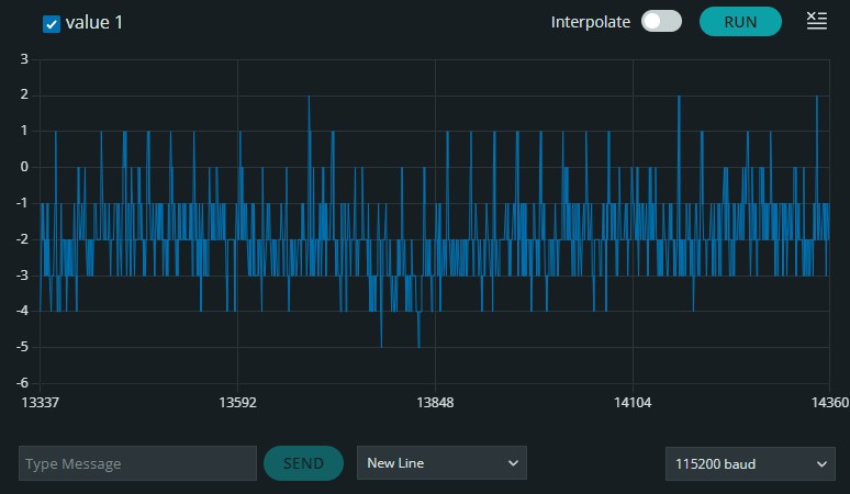
Thank you for confirming. I am sampling at 1 kHz, because i need to accurately capture signals with frequencies of a few 100 kHz. At this point, my actual needs are not fixed yet, as my sensor circuit can still be adapted perhaps to include an external amplifier, which would allow me to reduce ADC gain and reduce the impact of this noise (though now that I think about it I should also test that to see if the gain reduction also reduces this noise or not). Currently I have simply put together a prototype sensor as a proof of concept and my full range on the sensor was only about 80 mV, so this noise was very noticeable. I was also intrigued by the fact that there were significant diferences between boards.
In the future I will probably design my own PCB using the nRF54L15 and thought that I could learn something from this case in order to avoid such noise in my own design.
EDIT: Just did a quick check and yes, the BLE noise is also reduced by reducing the gain.
Hi, thanks for the offer, I’d love to see the results from the TAG as well. The serial output is simply 1024 samples every 10 seconds, but you might need to check which pins are available for SAADC.
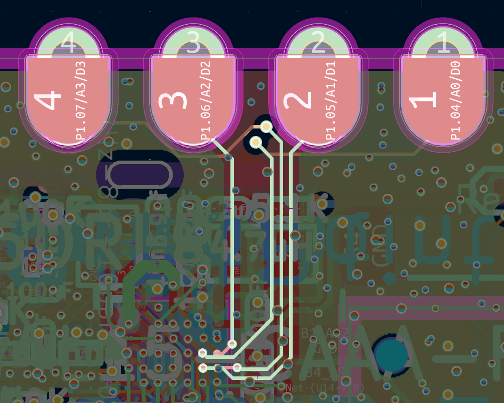
Related to that. A colleague suggested that I try different channels. It turns out that AIN2 is the only problematic one. When AIN2 is included in the measurement I get noise, with all the others the noise is greatly reduced or even unnoticeable. I will take a look at the KiCad project to see where the trace is routed.
It seems that they all follow pretty much the same path, under the main power supply inductor, though the A2 does go a bit more to the left so that could mean a bigger loop when combining A2 with any other analog pin.
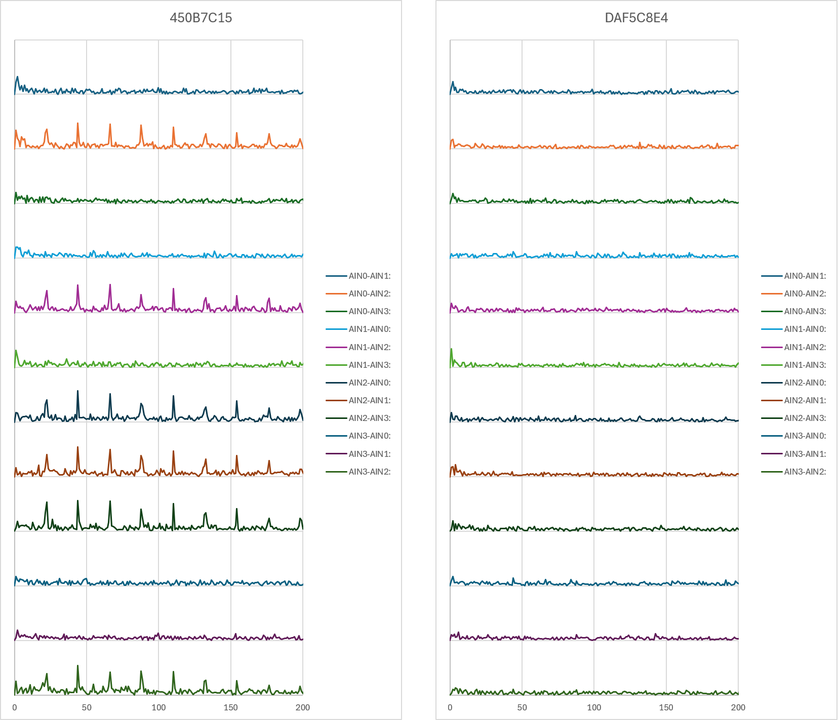
Here is also a cross check of every AIN combination, the graphs are FFTs, and I checked two boards, one that I know has a lot of noise and one that doesn’t. The layout should be the same on all of them so that itself doesn’t explain the difference between the boards.
Hi there,
So , Yes the DAC’s are 14 bit on the L15, and Honestly those charts look very CLOSE to normal? but the spikes, Hmmm…
I wonder if the battery voltage(reader) divider tech they are using is partly responsible , isn’t there a ADC being used there too? A2 & A3 ?
Hard to think the dev environment could have this effect, I just ordered 2 more L15’s and 4) LM20A’s for upcoming projects. I’ll shake them down too ,see what comes out.
HTH
GL  PJ

We should have a seeedineer on the thread so, see what they can offer info wise, 
Hi there,
So those 2 new Xiao , you have do you have the packages still ? Do they show the date code’s? Can you post a picture of them ?
I think everything we do can help clear it up and get to the bottom of it,
will make us a better product from them. I feel now like it’s a marginal component they may have used during chip shortage ? the date codes may help if they audit the BOMs and indicate the change 
GL PJ
It has become clear that there are differences between individual XIAO units, and even within a single unit, there are variations depending on the specific pin. It’s hard to imagine why there would be such significant differences in an electronic product.
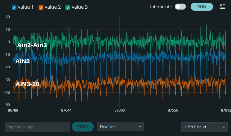
Of the four XIAO units I own, I used the one with the most noise to perform single-ended A/D conversion on AIN2 and AIN3. Both exhibit spike noise in the same way, but there is a difference in the magnitude of the noise between AIN2 and AIN3. Even when using a differential (subtraction) configuration, some noise remains. Perhaps the results would be even better if the signal lines for AIN2 and AIN3 were routed in parallel as a pair on the circuit board.
Thank you so much for bringing this to our attention — we really appreciate you taking the time to report it! 
Right now, our team is looking into this and working hard to reproduce the issue on our end. If you notice anything else or have more questions down the line, please don’t hesitate to share them all at once — it’ll help us get to the bottom of things faster.
Let me quickly answer a couple of questions while we’re at it: We recently pushed an update to the nRF54L15 schematic and KiCad project, bringing it up to version 1.2. The updated files have been synced to the Wiki too. If you picked up the board after August, just double-check you’re referencing the latest schematic file — that might be where the mismatch is coming from.
We’re on it and will keep you posted!
Hi there,
and welcome…
Names a little hard to say  , but glad the reinforcements are here,
GL PJ
Hi there,
sounds more and more like the (r) values of the volage divider they use for the battery voltage reading. may be no goood?
HTH
GL PJ
I want to try the LM20A , with the PMIC… bet it’s 100% better.
Hi everyone, thanks so much for your patience! I’m Brandy, and I’ve gone through all the test results you shared with our engineering team.
That said, we’re noticing a few things that are hard to pin down right now — specifically, the noise error range isn’t entirely clear from the current data. We’re also really curious about the A2 issue: is it something that only shows up under BLE, or does it also happen in normal/regular mode?
We’re working closely with our R&D team right now to run more tests and dig into this. Please bear with us for a little while — we’ll get back to you as soon as we have more concrete results!
Hi Brandy, thank you very much for taking a look at this. The example code that I uploaded has 14-bit resolution and 128x oversampling, to reduce the other noise to a minimum. The noise appears to be (perhaps directly, but more likely indirectly, through power consumption) caused by the BLE communication (most noticeable when connected and sending data) and can be up to 10 LSB, when the gain is set to 2x. When BLE is not active there is no noise.
Okay, we’ve received your reply. It seems that with your help, we can further pinpoint the issue. We will look into the root cause of this problem shortly.I see you’ve also ruled out the hypothesis that this issue was caused by the layout routing diagram.
That part is hard to confirm for me. The routing could be a contributing factor given that A2 is routed away from all the others, but it doesn’t explain the difference between boards.
Okay, I understand. It’s totally fine, and thank you so much for bringing this issue to our attention. If there are any related problems, we’ll just get to the root of them. Once the engineers verify it, this will also be fixed in subsequent versions. Thank you again very much for pointing this out.
… i thought you were a scammer or AI with that username… lol