Battery Operation Issues with ESP32S3 Xiao

Hi everyone,

I’m diving into an exciting project where I aim to utilize the ESP32S3 as a controller for my Automatic Chicken Feeder. The design involves powering the controller via a rechargeable battery system.
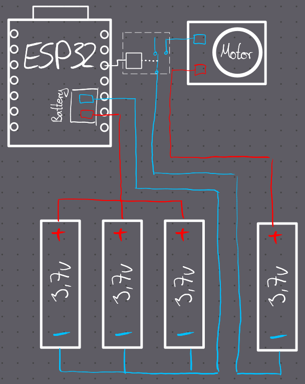
Project Setup

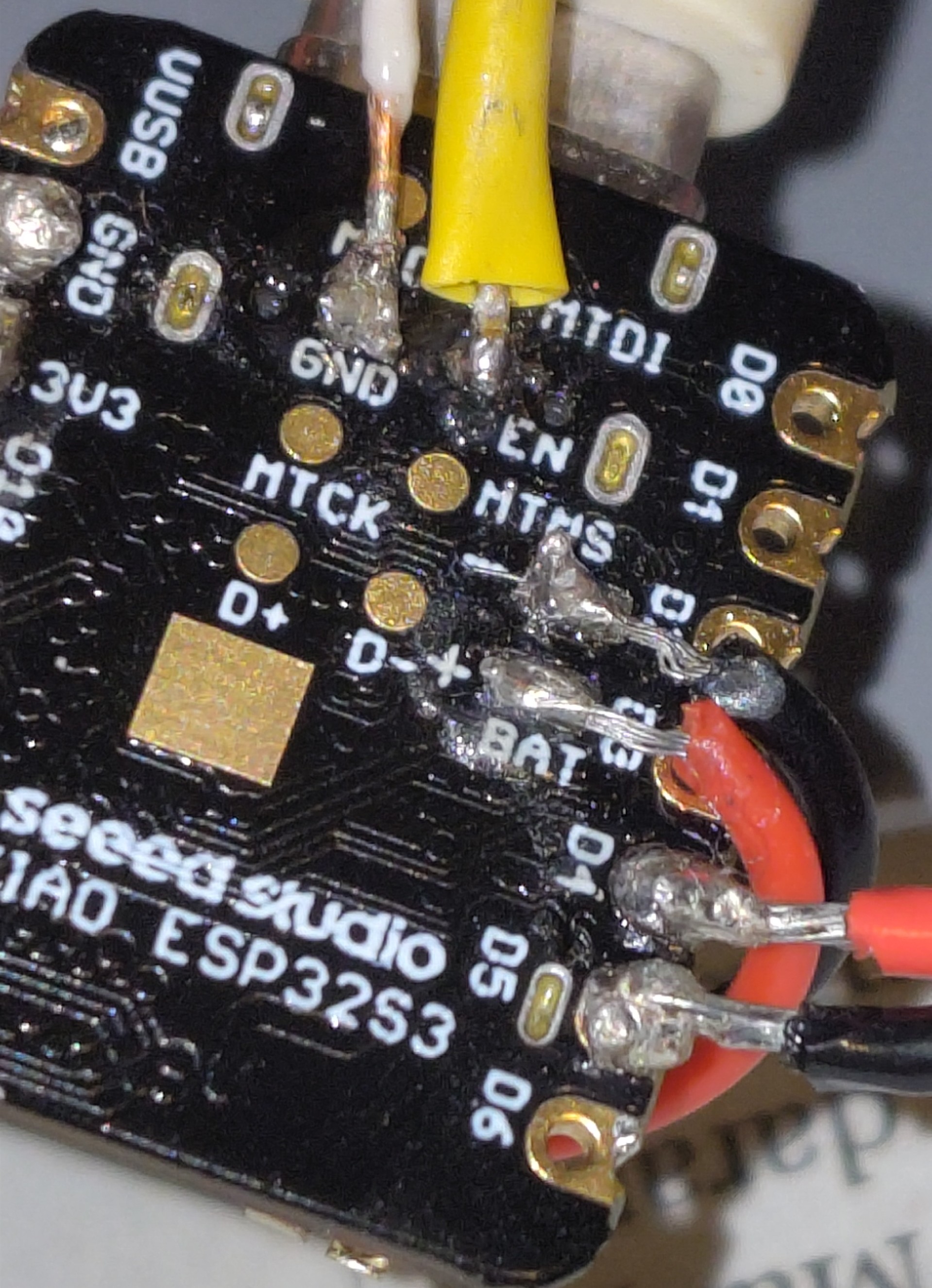
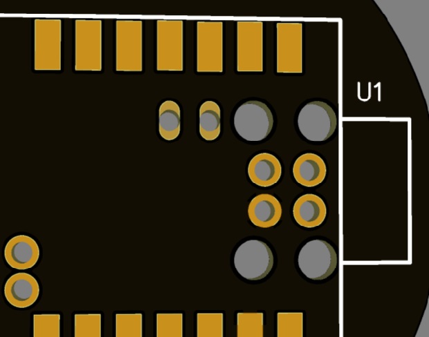
  • Controller: ESP32S3 xiao
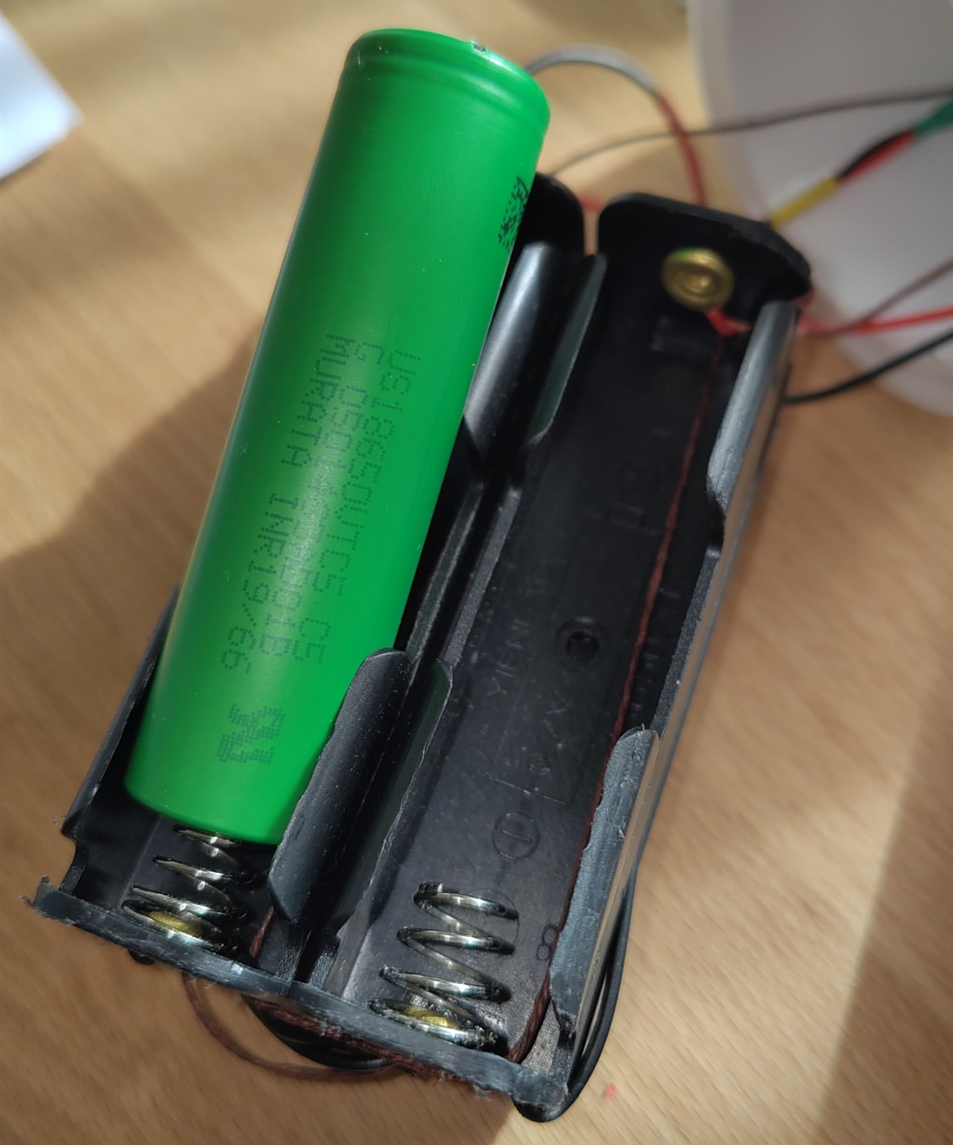
  • Power Source: Three rechargeable 3.7v lithium-ion batteries

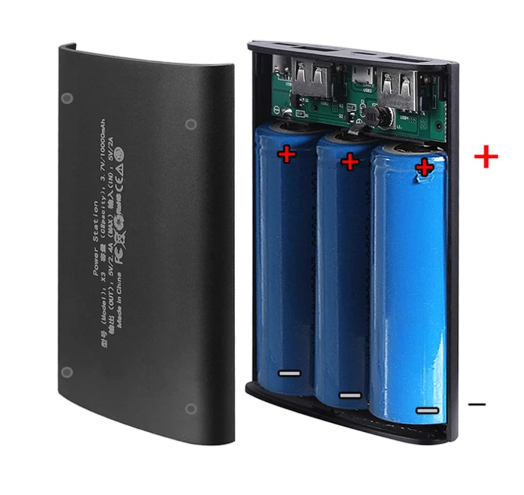
Battery Configuration

Based on the guidelines provided on Seeed Studio’s wiki, I assembled a battery pack with three 3.7V lithium-ion batteries. Initially, everything seemed functional:

  • When connected to my laptop via USB, the ESP32S3’s charging process was indicated by a blinking power LED.
  • The device was able to communicate over the serial interface.

Issue Encountered

However, upon unplugging the USB-C connection, the ESP32S3 shuts down unexpectedly. There are a few observations to note:

  • The power LED remains dimly lit in battery mode.
  • The device fails to initiate the WiFi Access Point, which is crucial for my project.
  • Attempts to reboot or reset using the onboard buttons have been unsuccessful.

Seeking Assistance

I’m reaching out to see if anyone in the community has faced similar issues or could offer insights into what I might be missing in this configuration. Specifically, I’m looking for advice on:

  • Power Management: Are there any steps I’ve overlooked in the battery setup?
  • ESP32S3 Configuration: Could there be specific settings that need adjustment for optimal battery operation?
  • Troubleshooting Tips: Any suggested methods to diagnose or resolve this issue?

I appreciate any guidance or suggestions you can provide. Thank you for your time and help!

Best regards,
Friedjof

Hi there,
Wow, Nice project. 3D printed too, nice work.
I see the code , looks good too. Why not use WPS method for WiFi? no credentials to enter then just push the button.
Do you have a picture of the batteries and the connections?
Have you tried a small USB Power pack as a test?
HTH
GL :slight_smile: PJ :v:

Thanks for your quick reply. The project is still a work in progress, so there are still areas that need to be worked on.
Unfortunately, the soldering points didn’t turn out very nicely, but my soldering iron is a bit too big. However, it holds firmly and the power definitely gets through. I measured it and the power LED also lights up.

ESP32S3.jpeg

Best regards
Friedjof

Ok,
Yea, get a smaller Iron. You may consider making a PCboard, just put holes in it below the battery terminal and fill with solder, acts as a mount too, see here.

e5

Ok so the “Battery PAK” is the issue, are you saying you put 3 battery’s together?
Let’s see that art work. I would bet you exceeded the max on the PMIC if so.
Did you top or bottom balance the batteries. , Do they power the whole system?
HTH
GL :slight_smile: PJ :v:

I have a pack of 4x 3.7V batteries. Three of these are powering the ESP32S3, and the fourth one supplies power to the motor (refer to the diagram).

Hi there,
wOW, Ok that looks like the issue,
First thing I see is the relay powering the motor have a GND connection, I see the signal energizing it , why is it connected to the 3.3v? The 3 batteries in parallel have no Battery manage ment IC or balancer. You can use it that way. Each battery has an internal (R) they won’t all discharge or recharge at the same level and rate. Once one is low they will all be low trying to self ballance. No that’s not a proper Battey setup.
ALso I would place a clamping diode across the motor relay as to not generate any Reverse spike when energised also Not a real good Idea to switch the Ground leg of the motor , when disconnected it’s sitting at the 3.3v potential and not good for Lightning or Static electric discharge could move motor randomly if high enough. Switch that and use the diode IMO

Also in this setup the motor battery doesn’t get recharged?
so I’m guessing this is only a sketch not the real schematic?
What is the power requirements or power profile of this setup?
How long does the battery last currently?

Awesome real world project. :+1:
HTH
GL :slight_smile: PJ :v:

Why not something like this to power it? Even a Solar version of this too.

Hi there,
Thank you for the detailed feedback! I’d like to address your points with some clarifications.

Regarding the motor, it’s capable of handling more current, up to 12V, but the current speed is just right for my project’s needs. The relay depicted in my sketch simplifies the actual setup – in reality, it switches the positive pole, not the ground. Also, it’s a standard commercial relay, already equipped with multiple protective mechanisms, capable of handling up to 230V.

About the battery management, I must admit that I’m not very experienced in this area. I thought the batteries would naturally balance themselves. Space is a significant constraint in my design, as the round box I’m using just fits the 4x 3.7V battery pack, without any room for a proper battery management system. I’m only able to place two batteries side by side due to space limitations. However, I’m open to adding the right ICs for better power management and would appreciate any recommendations you might have. Initially, I assumed the ESP would simplify many of these tasks.

Concerning the separate battery for the motor, it does deplete slowly, and I plan to recharge it manually, though I acknowledge this isn’t the most optimal solution. I had to isolate this battery from the others because connecting them resulted in a significant voltage drop, adversely affecting the ESP.

As for the battery life with the ESP32-WROOM, it lasted around 3 to 4 weeks. The regulator, a cheaper variant from China, was quite power-hungry and tended to get warm. Now, with the ESP32S3 Xiao, I won’t be needing that specific regulator, which leads me to anticipate a longer battery life once everything is up and running.

I look forward to any further suggestions you might have, and thanks again for your help!

Best regards,
Friedjof