Hey all, looking for some help with addressing 2 OLED displays with my Arduino UNO + Grove base shield.
The displays in question are these: Grove - OLED Display 0.66" (SSD1306) | Seeed Studio Wiki
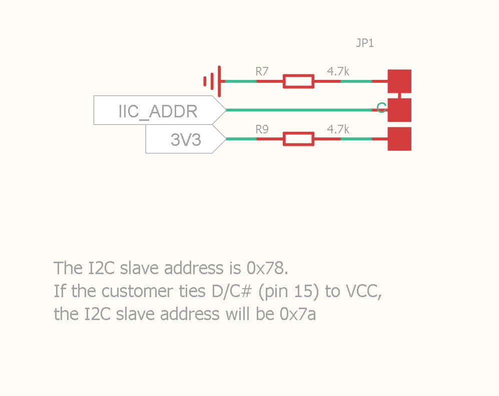
The features clearly state: “Changeable I2C address”, but little information on how to achieve this exactly.
I’ve tried soldering the pads on the back of the PCB of one display to select 0x7A (i.e. 7 bit 0X3D), but when I run an I2C address scanner, I still only pick up 0x3C address.
This is pretty frustrating as I thought I did enough research before buying these displays, but now I don’t seem able to actually change the address.
Any help with these, or similar would be greatly appreciated.
P.S. sorry I’m new to Arduino and Grove, so apologies if I’ve messed up some of the technical details.
Cheers,
Mark.
HI there,
and Welcome…
You got a picture of the setup? are they like these here in the grove expansion demo? I think they are similar, I see that you must cut and solder, you see that? to change the address of one of the units,
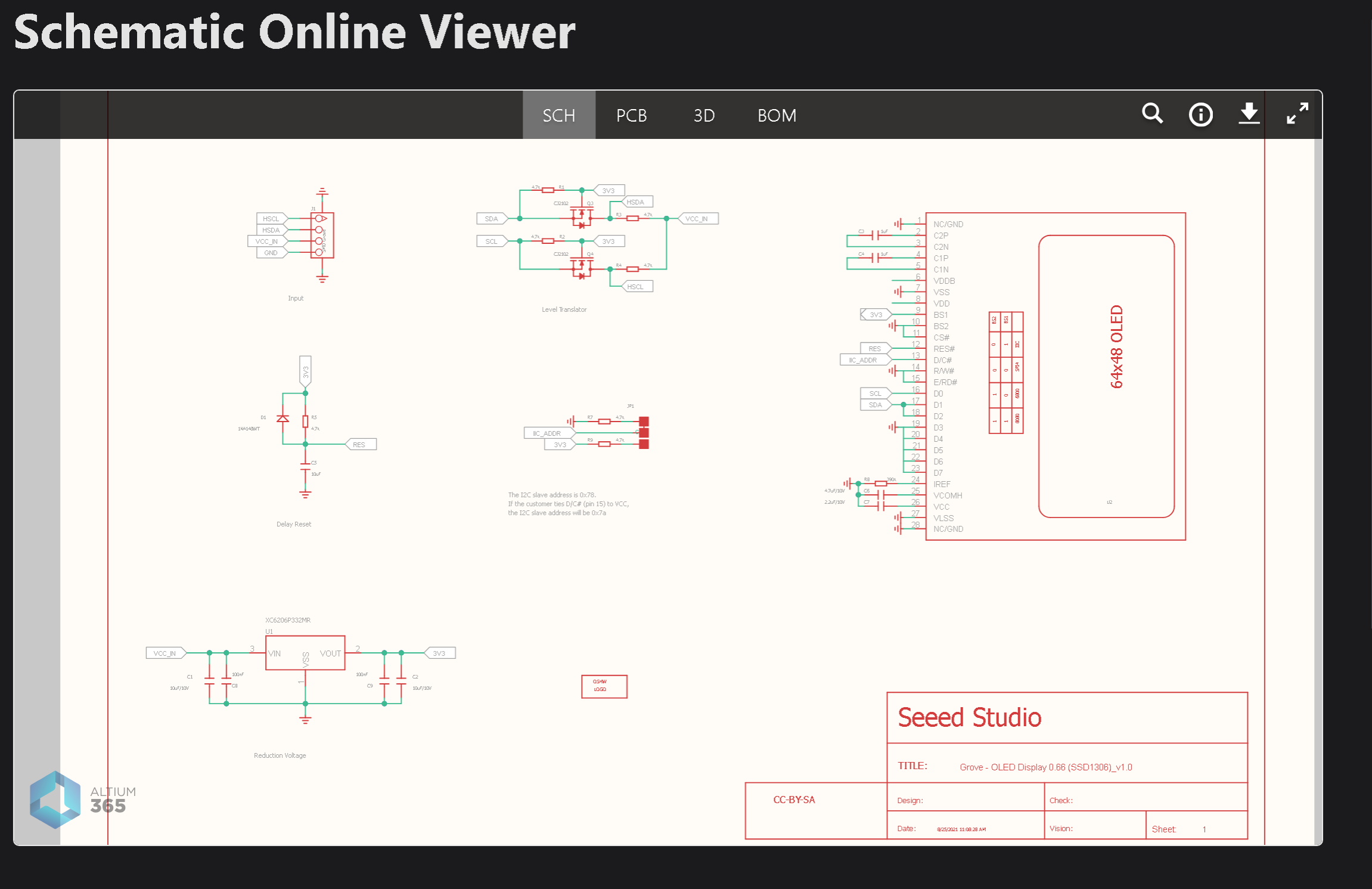
from thew online schematic viewer from the wiki
Do you have the code to drive them, As in each display is instantiated as a display, display2 ?
HTH
GL

PJ
Thanks for the quick response @PJ_Glasso.
The displays are similar to what you linked, but not exactly the same.
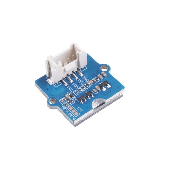
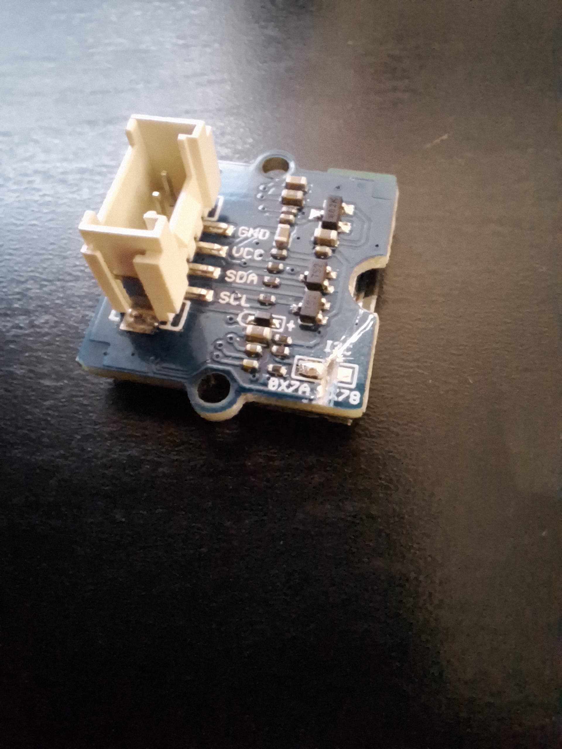
The image below shows the back of the display. In the bottom corner are the pads I understood were where I could change the address.
I’ve soldered the two pads together for 0x7A address. I couldn’t see any existing trace for the other address, but I cut between the pads anyway. I could very well have messed this up, but just wanted to confirm this is the way to do it.
Here is my code for testing the displays, both always show “Disp 1”. Note, an I2C scan does not show two addresses, so my understanding the issues is in the hardware, not the software.
#include <U8g2lib.h>

// Setup OLED displays

U8G2_SSD1306_128X64_NONAME_1_HW_I2C  disp1(U8G2_R0, /* reset=*/ U8X8_PIN_NONE);

U8G2_SSD1306_128X64_NONAME_F_HW_I2C  disp2(U8G2_R0, /* reset=*/ U8X8_PIN_NONE);

void setup() {

 // put your setup code here, to run once:

 disp1.begin();

 disp2.setI2CAddress(0x7a);

 disp2.begin();

}

void loop() {

 // put your main code here, to run repeatedly:

 do {

   disp1.setFont(u8g2_font_ncenB10_tr);

   disp1.drawStr(33, 50, "Disp 1");

   disp2.setFont(u8g2_font_ncenB10_tr);

   disp2.drawStr(33, 50, "Disp 2");

 } while (disp1.nextPage());

}
Confirm that you are using the correct I2C address scanning code. Here’s a simple Arduino sketch you can use to scan for I2C devices and their addresses:
#include <Wire.h>

void setup() {
  Wire.begin();

  Serial.begin(9600);
  Serial.println("\nI2C Scanner");
}

void loop() {
  byte error, address;
  int nDevices;

  Serial.println("Scanning...");

  nDevices = 0;
  for (address = 1; address < 127; address++) {
    Wire.beginTransmission(address);
    error = Wire.endTransmission();

    if (error == 0) {
      Serial.print("I2C device found at address 0x");
      if (address < 16) Serial.print("0");
      Serial.print(address, HEX);
      Serial.println("  !");
      nDevices++;
    } else if (error == 4) {
      Serial.print("Unknown error at address 0x");
      if (address < 16) Serial.print("0");
      Serial.println(address, HEX);
    }
  }

  if (nDevices == 0) {
    Serial.println("No I2C devices found\n");
  } else {
    Serial.println("done\n");
  }

  delay(5000);  // Wait 5 seconds for next scan
}
Upload this sketch to your Arduino UNO and open the serial monitor. It will scan for all devices connected to the I2C bus and display their addresses.

If you still only see the address 0x3C, double-check your soldering and make sure you're scanning the correct bus (sometimes there can be multiple I2C buses on certain boards).
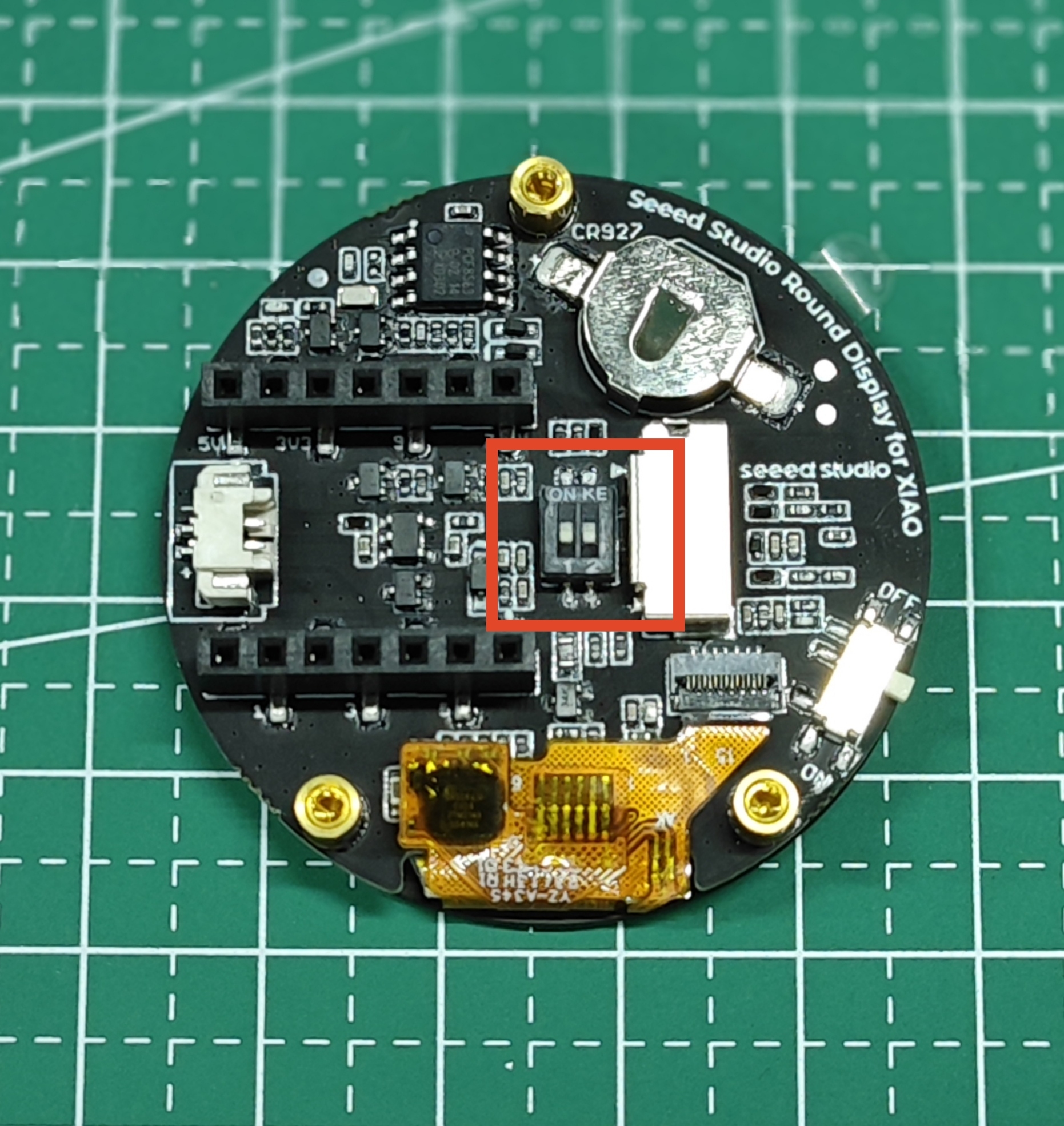
I wish seeed would add a simple micro dip switch or something to make this easier
similar to
Hi there,
Yes, YOU must cut in between the other two, You got it correct.
I would use an example code that runs on the display as default first. Once you have an image change the code to the second address and try the modified display. Does it work, If so Proceed. If not Figure out why.
Single display and demo code, First. GO!
HTH
GL PJ
" a switch would make it cost a .001 cent more"…LOL
Thanks everyone, I really appreciate the input you’ve all given me.
I have been testing with just a single display and the modified screen still only responds on the original address (thanks @liaifat85 I tried your code directly as well). Seems as though I’ve haven’t done the soldering correctly. I mostly wanted to check I haven’t missed something.
I 1000% agree with you @cgwaltney! Why oh why, couldn’t they have just used a switch? I bought into the Grove ecosystem because I didn’t want to have to rely on my terrible soldering skills  . I guess for 99% of people, using a single display this isn’t an issue.
Thanks PJ, I decided to experiment with the other display to see if I could get any change in behaviour.
I placed a cut between the two pads (address 0x78), with no solder, and there was still no change. I would have thought there would have been an error or something right?
I also tried placing a small screwdriver across the pads with no effect. Are there any other tests like this to see if these pads actually do anything?
The “Changeable I2C address” claim on the product is starting to feel a bit false.
Hi there,
Yes I would agree, How ever it may be It needs Initialized at that new Address for it to stick?
You are on the hunt for sure, Good you have more than one to try.
I had 2 working on the Expansion Board a while ago so may be a post on here with the code I used.? I did work though forsure,.
HTH
GL PJ
Your close you will get it… 
Unfortunately this has defeated me. Here’s a photo of my end result:
Ugly I know, but I was determined to keep cutting until I got some change in behaviour, or broke the display. Neither happened 

I think I’m just going to go with the I2C multiplexer now. If anyone has had any success changing the address with this specific display, I would love to learn how to do it properly.
Thanks again to everyone for their input and encouragement.
Cheers, Mark.
Hi there,
uch, That definitely Voids the Warranty 
That was a TAD too many foot-pounds there. probably damaged the trace below, but I think.
"Well if you’re gonna make an Omelette you must Break a few Eggs " so to speak.
We all been there. Does it still work at all?
Get another, they are plentiful and cheap. (no grove connector)
The multiplexer is unnecessary, I’ve seen vids of 4 displays at once with-out it, btw.
HTH
GL PJ 
Yeah it still works. Just to clarify, it didn’t look like that in the beginning. That’s a result of my frustration, haha.
1 Like
i hate to be a Di=k, but this video shows changing the address,
but i do believe i have seen multi displays too, somehow they draw a bigger resolution screen and scroll the image or something
another way to do it is to set up an additional IIC port
one will be a hardware IIC port and the second will be a software emulated IIC port
then you can instantiate a hardware and software IIC display and write the data to each independently at the same address
Thanks @cgwaltney, that sounds like a neat solution, but given I couldn’t even do a simple thing like change the i2c address, that is probably beyond my capability.
In this case it will be easier for me to just throw some money at the problem, and/or adjust my design to only use one screen.
Perhaps I can solve these problems more effectively after I get some more experience.
1 Like
i will try and see if i can figgure it out myself, lol
I think using an I2C multiplexer will be a better solution.

_V1.0/img/10402049_Back.png)
