Hello Lygra & Slimfish & everyone here,
I’m trying to learn / understanding what you guys are talking about in this thread. So please bare with me.
I’m interested in how to change the T/Div?
On my DSO quad with sys 1.34, I’m using the square wave generator of the quad to test the quad itself.
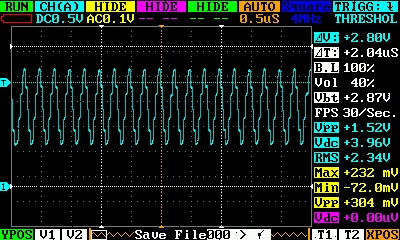
With 4Mhz square wave, and with the time div 0.5us, and with the voltage div of 0.5v the signal looks like a lot of stepped sine wave. (Please excuse me if my terminologies are not correct. I’m not an EE). The peak to peak voltage of the signal reported by the DSO is 1.52v
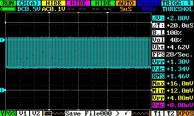
Any bigger time div (5uS) for example, the wave appears to be square pulses, but it’s not detailed enough and probably is useless. What do you think?
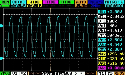
With 2MHz wave, the signal looks like this:
It looks better, but still like sine.
So how do I set the T/div to make it look square? Thanks very much!
Now base on the voltages I got: Vpp = 2.58v @ 2MHz vs Vpp = 1.30v @ 4MHz, what do I make of the bandwidth?
Thanks
-Thanh
ps. I saw this link last year when I first heard about the DSO Quad, and I was searching for what 36Mhz sample rate can measure:
emcsociety.org/Presentations … 0Radar.pdf
It looks like the effective bandwidth is about 36Mhz / 5 =~ 6Mhz?
Now if the effective rate is down to 15MHz, then am I right that we can only measure around 2.5Mhz?