
I received one of these recently (via Seeed Studio). Everything works except for PoE and I am wondering if I have missed something?
This is the device <LINK_TEXT text=“https://www.seeedstudio.com/Raspberry-P … -4370.html”>https://www.seeedstudio.com/Raspberry-Pi-Compute-Module-IO-Board-with-PoE-Feature-for-Raspberry-Pi-CM3-CM3L-CM3-CM3-L-p-4370.html</LINK_TEXT>
I have moved the PoE jumper from DIS to EN.
Then plugged in a PoE lead coming from a TPLin PL-PoE1505 PoE Injector (it is 802.3af compliant). I get nothing on the board, and the TP-Link device (via a green flashing led) indicates no power being consumed/delivered.
There is no voltage on the test point (24) on the board.
I have tried two other PoE supplies, but they also do not work with the board.
Is there some other step I need to take, or do I have a faulty board?
The board works fine on USB Power, but I purchased it for the PoE capability!
Thanks in advance!
Hi,
When I looked at the Compute Module PoE Board Documentation , It says When using PoE function, this module supports 27V ~ 57V input, and voltage output is 5V and 2.5V. so can you check the Input Voltage of PoE in Pi Module
The voltage is 48V on all of my PoE supplies (Netgear, TP-Link and Unifi). I know they all work fine. With the PoE jumper set to EN there is no voltage (5V) at the Test Point (24). So I have a feeling I either need to set something differently, or there is a fault somewhere on the board.
Oh, that looks strange. can you test the pads with a multimeter and trace the PoE pins to check the voltage.
The voltage is zero. It’s incredibly hard to trace anything on the board - the circuit diagram does not give any physical clues away at all.
I know my PoE switch is successfully outputting the 48V. The position of the POE DIS/EN jumper makes no difference when I am powering from the micro-USB port.
I think the board must faulty somewhere in the PoE circuitry!
Ok, for more inspection you can use the Compute_Module_PoE_Board Shematics
Too complicated for me actually – and It’s difficult to trace down to the physical components from the schematic.
Did you solve the problem? And if yes, how did you solve it?
Hi @Hunlex
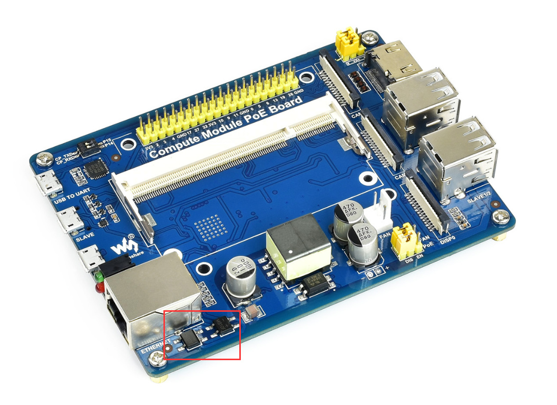
If you are using the previous Compute Module PoE Board, the compatibility may not be very good. Please photograph the front and back of the PCB so that we can determine whether it is the previous version. There will be two more devices in the latest version, as shown in the figure below.
Hi,
thank you for your answer! I think, I have the previos one because the both bridges are not included.
I found, that my switch needs to communicte with the device, if i use an injector, which always give the voltage, the board is working …