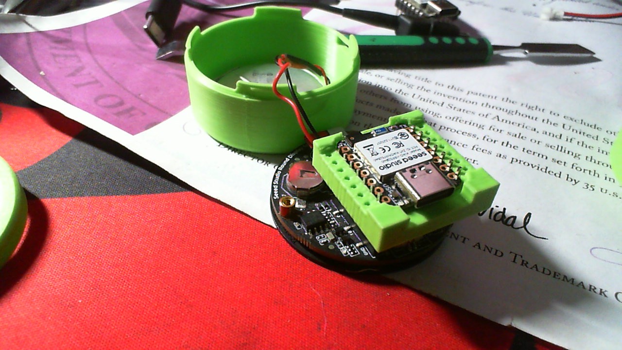
I have just received my XIAO.
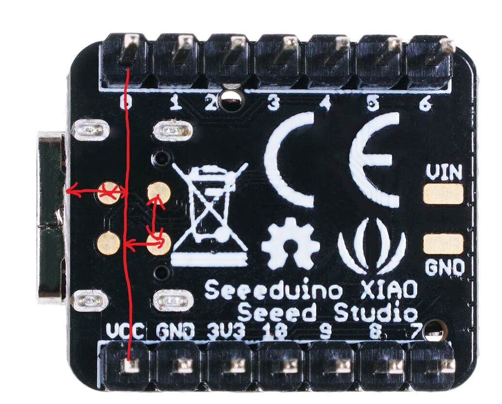
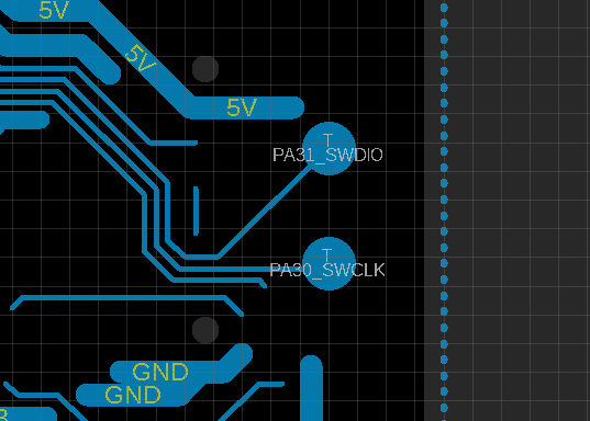
What I found awesome is that there are SWD I/O are exposed, but on testing pads.
I would like to know if you could provide an Eagle library with SWD pad footprint or any simple solution which could cleanly expose those pin to a standard SWD 10 pins connector (I don’t wan’t to solder crappy wires on the pads.), because the SWD pads are not aligned on a 2.54mm grid.
I could eventually make a custom carrier board. Which connector do you use on Seeeduino XIAO Expansion board (spring contact)?
Glad to know that you find the exposed SWD I/0 design useful for you.
The spring contact we use in SeeeduinoXIAO Expansion Board is customized, and purchased from designated contributor at a minimum order quantity. It well fits pin header of both 6mm and 5mm height. If you think SWD function is necessary for you, it would be highly recommended that you get one.
I have already seen the Expansion board, but not available yet. Also I would like to design my own expansion board, so I’ll need dimensions or any informations to be able to connect the SWD pins.
You can order similar things like the Mill-Max 827-22-004-10-001101. But stock and prices are all over the place. Also, it’s still tough to get the right height.
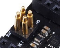
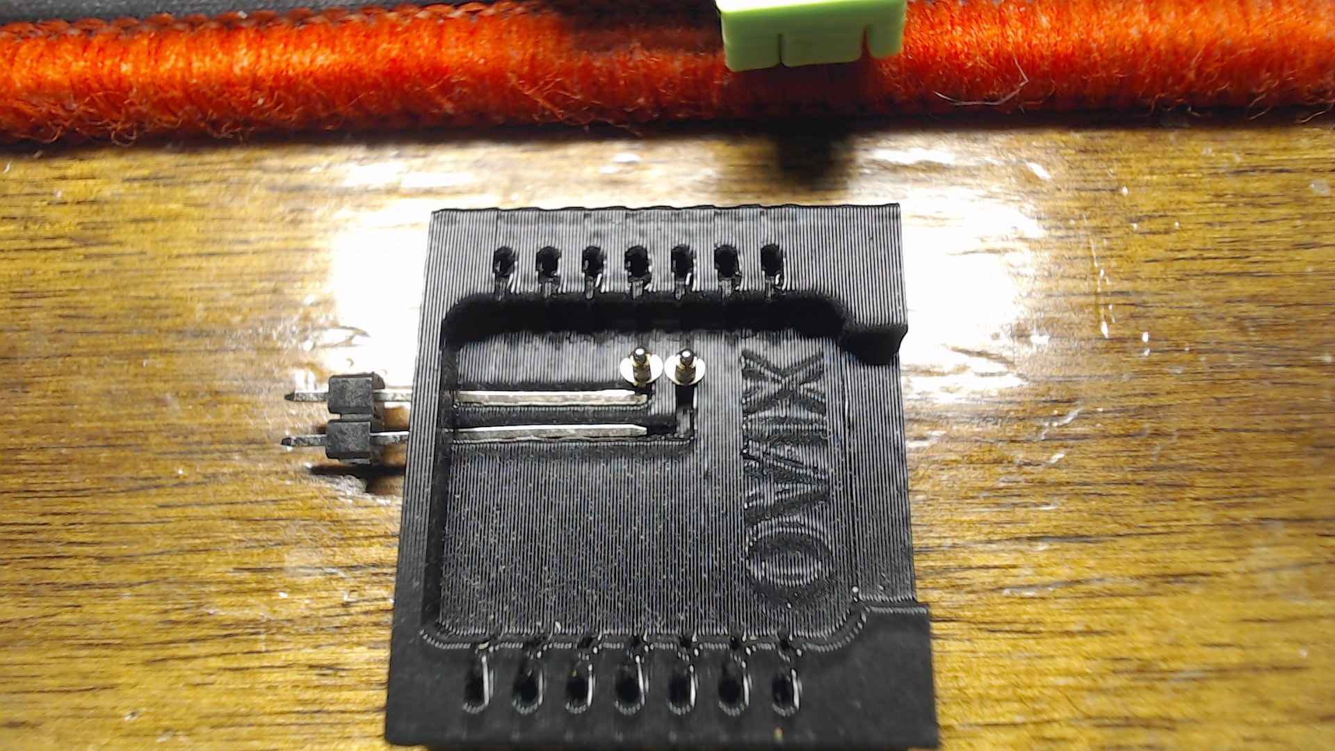
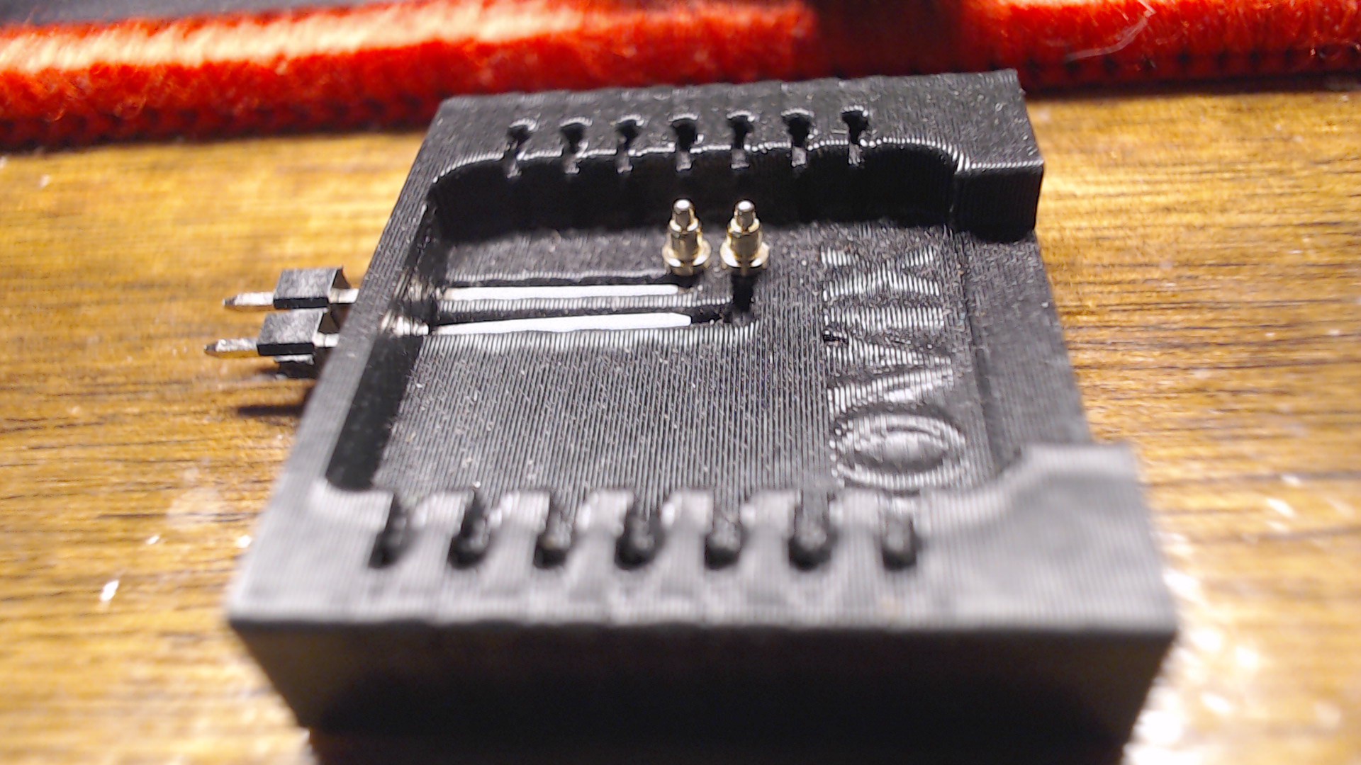
Adafruit 5382 is an inexpensive 2 x 3 pogo. You can carefully push out two pins, cut through the holes with dykes, then dress with a file.
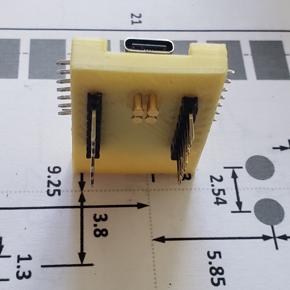
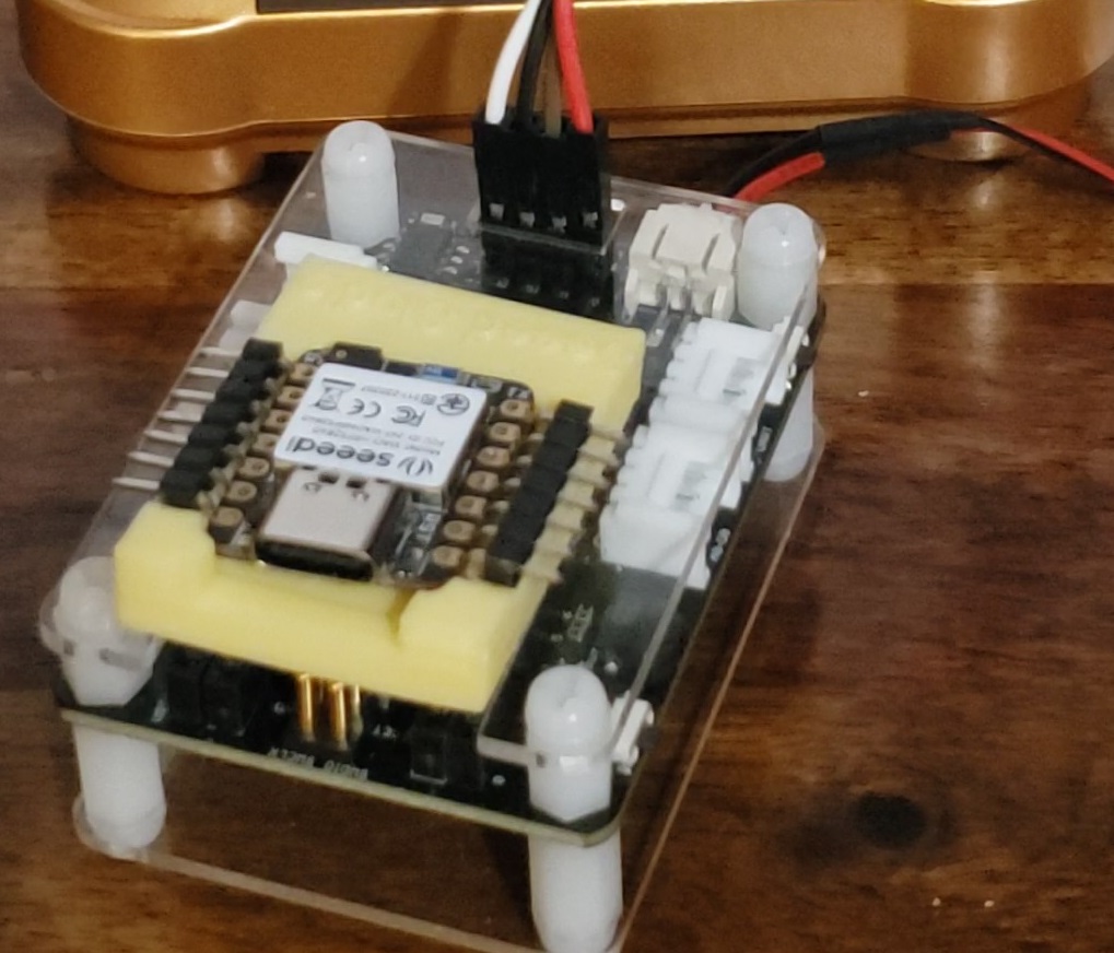
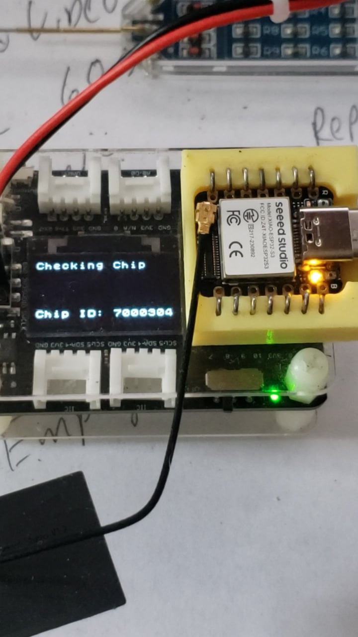
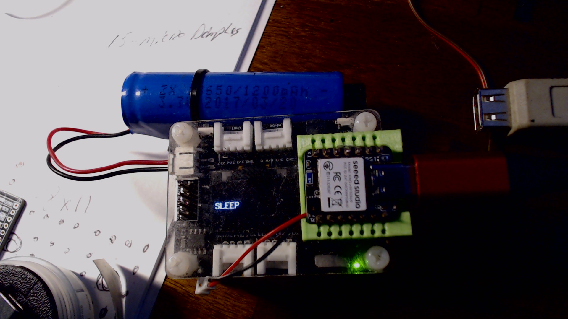
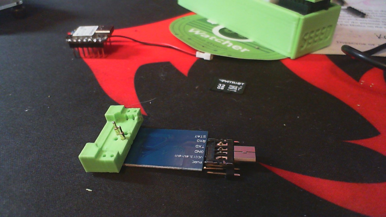
The layout of the SWD is 0.1” but on an 0.05” grid so it does not play nicely with perfboards. Also, to mate with 8.5 mm female header supported boards it needs about 2 mm spacer. I printed a little U-shaped thing that fits tightly between the female headers. The centering in that direction is perfect. The positioning in the other direction can be adjusted and then a drop of glue does it.
I had some very nice photos but it won’t let me. In any case, it worked out great.
Spam protection thingy, maybe a couple more reply’s will get enough creds to post the pics, This area is probably the least addressed from maker or manufacture it get’s the "Rodney Dangerfield " , NO -Respect
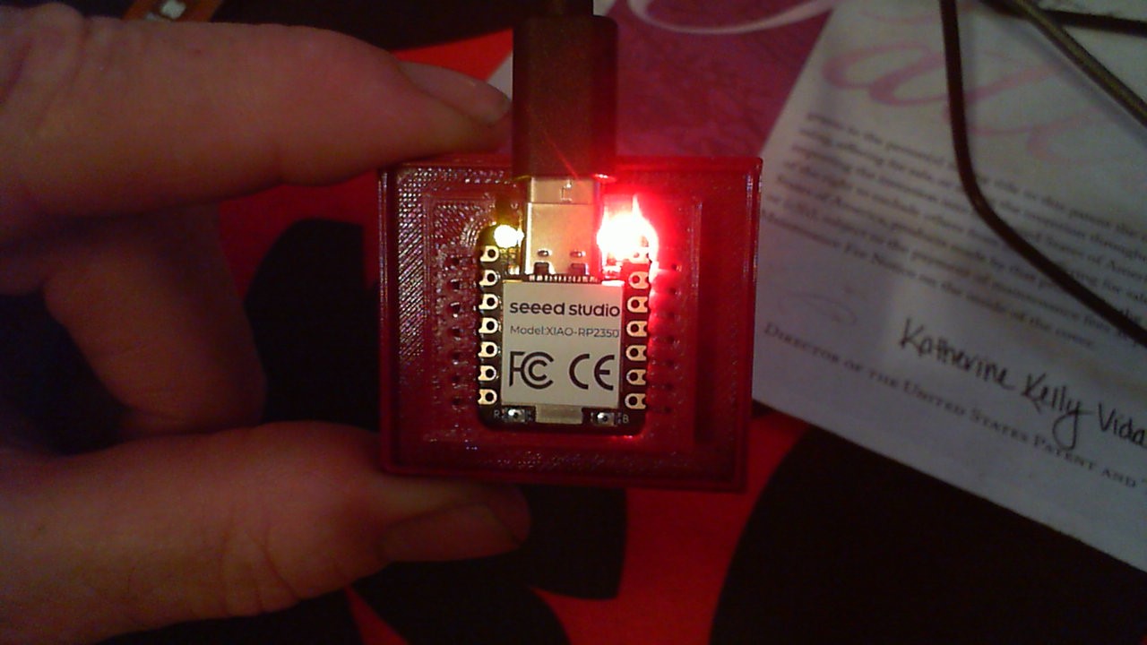
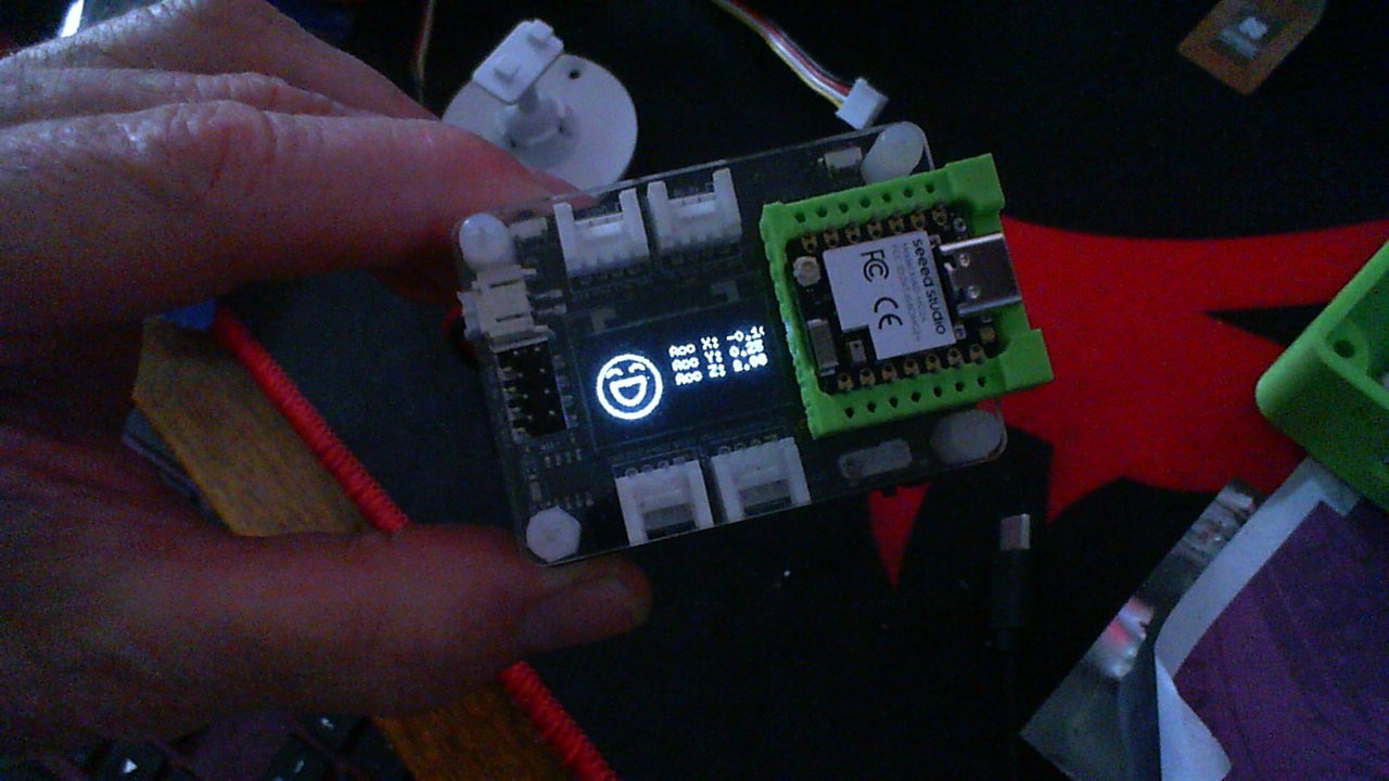
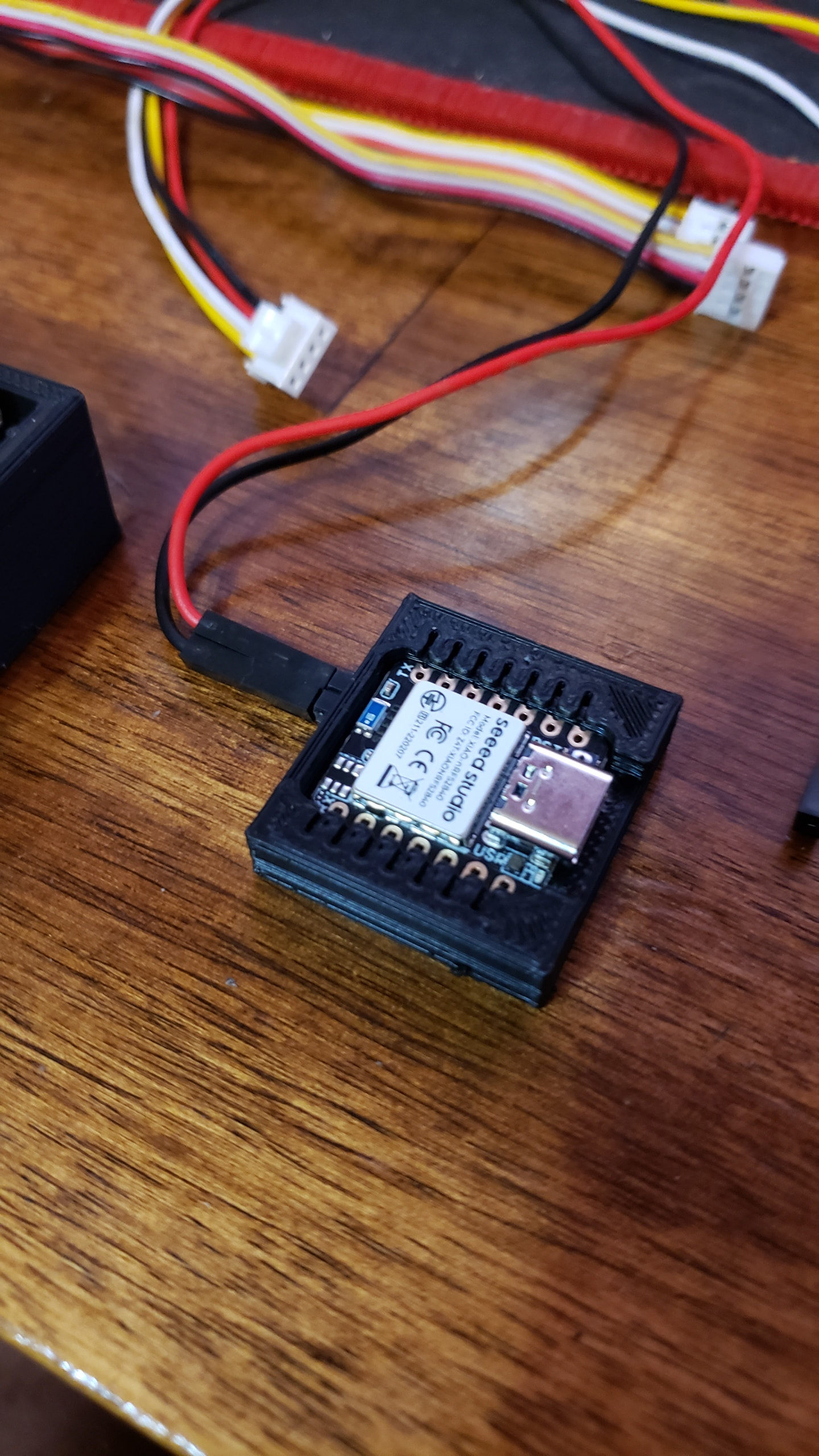
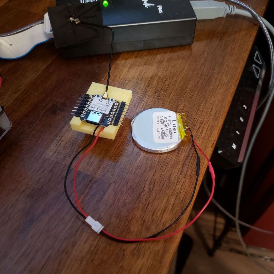
On my 3D printed sockets, I had similar but finally got it after a few prints