I’m attempting a ‘Blink.ino’ type sketch where a a small vibration motor toggles ON/OFF every 5 seconds. Despite the PIN changing voltage (confirmed with volt meter), it will not power the motor. This seems to be because the nRF52840 PIO pins are limited to 15 mA max, and the motor requires 19mA @ 1V to be noticeable.
The solutiom seems to be using a 2N3904 transistor to drive the motor, and only using the PIN to control the current flow at the transistor’s base. And this idea worked with the Adafruit Feather Sense nRF52840, but it won’t work for the Xiao Sense nRF52840
It seems the Xiao Sense is limiting the necessary current more than the Feather Sense and I’m not sure how to solve this now
My code is below. This works on Adafruit Feather Sense nRF52840 (just different pins). I’ve checked with a voltmeter that the pins on the Xiao Sense going to 3.3V, but still not driving the transistor
Here is my code:
void setup() {

  //#// Start Serial //#//
  Serial.begin(9600);

  //#// Set PINS at OUTPUT //#//
  pinMode(LED_BUILTIN, OUTPUT);

  pinMode(2, OUTPUT);                // Set 2 to OUTPUT (Vibrator Positive Lead)
  digitalWrite(2, LOW);              // Set to LOW

}


void loop() {
  // TURN ON
  digitalWrite(2, HIGH);             // Turn ON Motor
  digitalWrite(LED_BUILTIN, LOW);    // Turn ON LED during Motor ON
  Serial.println("Vibration ON");

  delay(5000);                       // wait for 5 seconds

  // TURN OFF
  digitalWrite(2, LOW);             // Turn OFF the motor
  digitalWrite(LED_BUILTIN, HIGH);   // Turn OFF the LED during Motor ON
  Serial.println("Vibration OFF");

  delay(5000);                       // wait for a second
}
PS: I even tried adding a second transistor such that Vcc even drives the base of the resistor driving the vibration motor, but this also did not work
Hi there,
The Xiao is Reverse Logic,
OUTPUT LOW Turns it “on”
Try that
HTH
GL  PJ
PJ 
Hi @PJ_Glasso, thanks for the reply. Unfortunately that didn’t work = (
Try this.
  NRF_P1->PIN_CNF[11] |= (GPIO_PIN_CNF_DRIVE_H0H1 << GPIO_PIN_CNF_DRIVE_Pos); //D6
  NRF_P1->PIN_CNF[12] |= (GPIO_PIN_CNF_DRIVE_H0H1 << GPIO_PIN_CNF_DRIVE_Pos); //D7
  NRF_P1->PIN_CNF[13] |= (GPIO_PIN_CNF_DRIVE_H0H1 << GPIO_PIN_CNF_DRIVE_Pos); //D8
  NRF_P1->PIN_CNF[14] |= (GPIO_PIN_CNF_DRIVE_H0H1 << GPIO_PIN_CNF_DRIVE_Pos); //D9
  NRF_P1->PIN_CNF[15] |= (GPIO_PIN_CNF_DRIVE_H0H1 << GPIO_PIN_CNF_DRIVE_Pos); //D10

  NRF_P0->PIN_CNF[2] |= (GPIO_PIN_CNF_DRIVE_H0H1 << GPIO_PIN_CNF_DRIVE_Pos);  //D0
  NRF_P0->PIN_CNF[3] |= (GPIO_PIN_CNF_DRIVE_H0H1 << GPIO_PIN_CNF_DRIVE_Pos);  //D1
  NRF_P0->PIN_CNF[4] |= (GPIO_PIN_CNF_DRIVE_H0H1 << GPIO_PIN_CNF_DRIVE_Pos);  //D4
  NRF_P0->PIN_CNF[5] |= (GPIO_PIN_CNF_DRIVE_H0H1 << GPIO_PIN_CNF_DRIVE_Pos);  //D5
  NRF_P0->PIN_CNF[28] |= (GPIO_PIN_CNF_DRIVE_H0H1 << GPIO_PIN_CNF_DRIVE_Pos); //D2
  NRF_P0->PIN_CNF[29] |= (GPIO_PIN_CNF_DRIVE_H0H1 << GPIO_PIN_CNF_DRIVE_Pos); //D3
Thanks @msfujino! This looks promising!
Can this be done with Arduino though?
Sorry, I’m away from the PC atm and can’t check the variant files easily, if that’s where this code would go
Thanks again
You can use it with ArduinoIDE without any particular #include.
If you are using mbed BSP, the output is STANDARD by default and must be set to HIGH.
If you use non-mbed BPS, the output is HIGH by default.
The following link is also for your reference.
“XIAO_nRF52840 mbed's SPI performance is only 1/3.5 of non-mbed's”
Thanks @msfujino for the explanation and the reference. I liked the analysis you performed in that post, it was helpful to confirm for my project that non-mbed is the right choice
But unfortunately I was already using the non-mbed bootloader so the output was already set to HIGH. I tried the code just in case, but it still didn’t work
It is strange that the Feather Sense with the same nRF52840 chip works, but the Xiao Sense won’t…even to turn on a transistor!
Any other ideas?
Please provide details on how to connect to FeatherSense (motor PCB, power supply or battery) and how to connect to XIAO Sense.
Let me see your sketch.
Testing power supply is USB, but I hope to use this with a 3.7V LiPo. Currently testing on a bread board
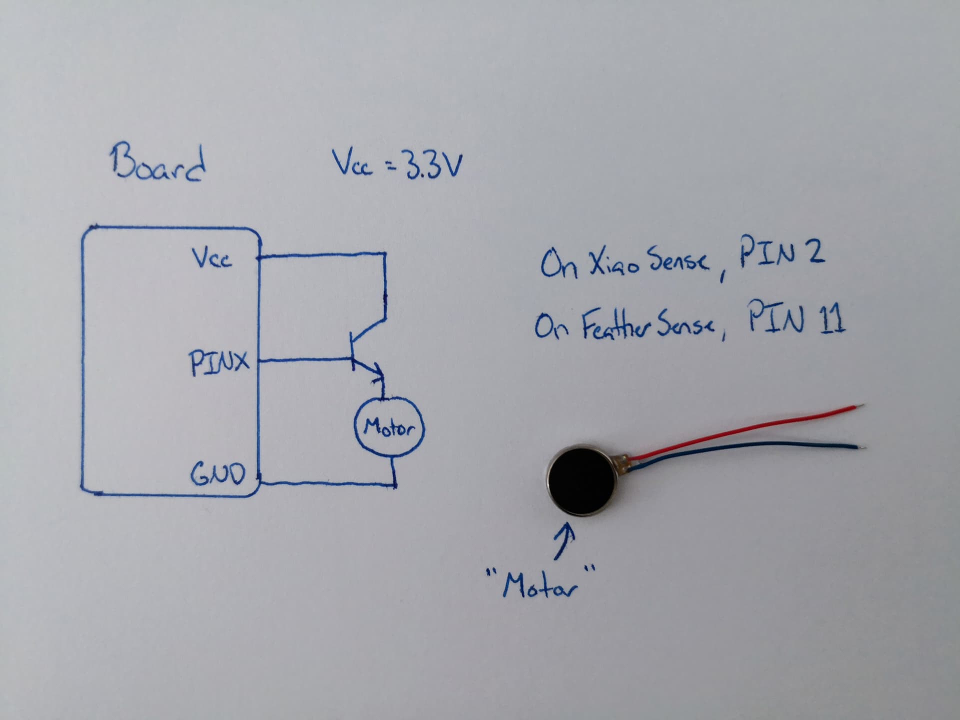
It is noted, the motor will run on the Xiao Sense if the transistor BASE is powered by Vcc instead of PIN 2. But it does not turn on for PIN 2.
It is confirmed with a voltmeter that PIN 2 is at 3.28 V when set to HIGH, but once it is connected to the transistor base this drops to 1.45 V
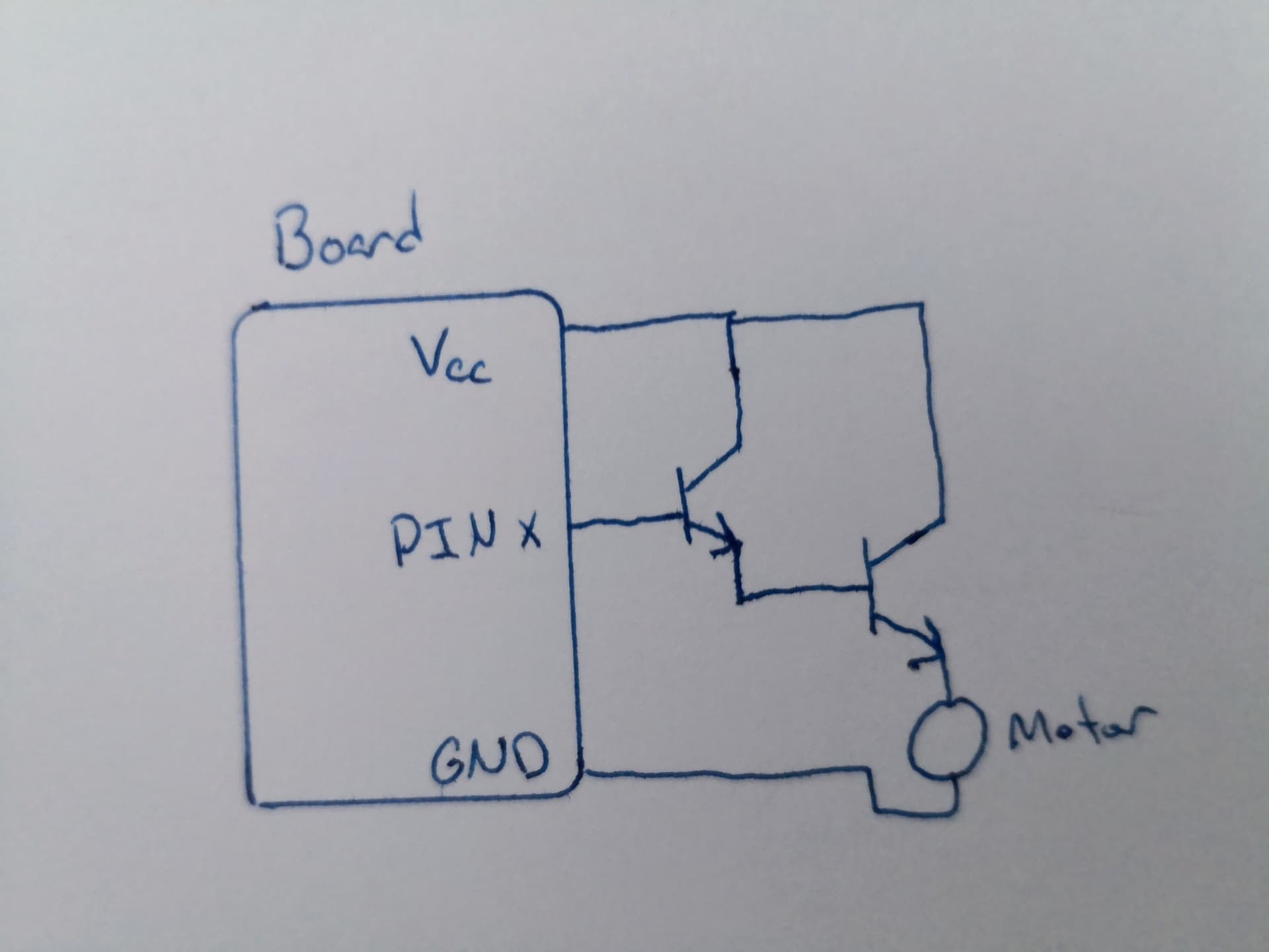
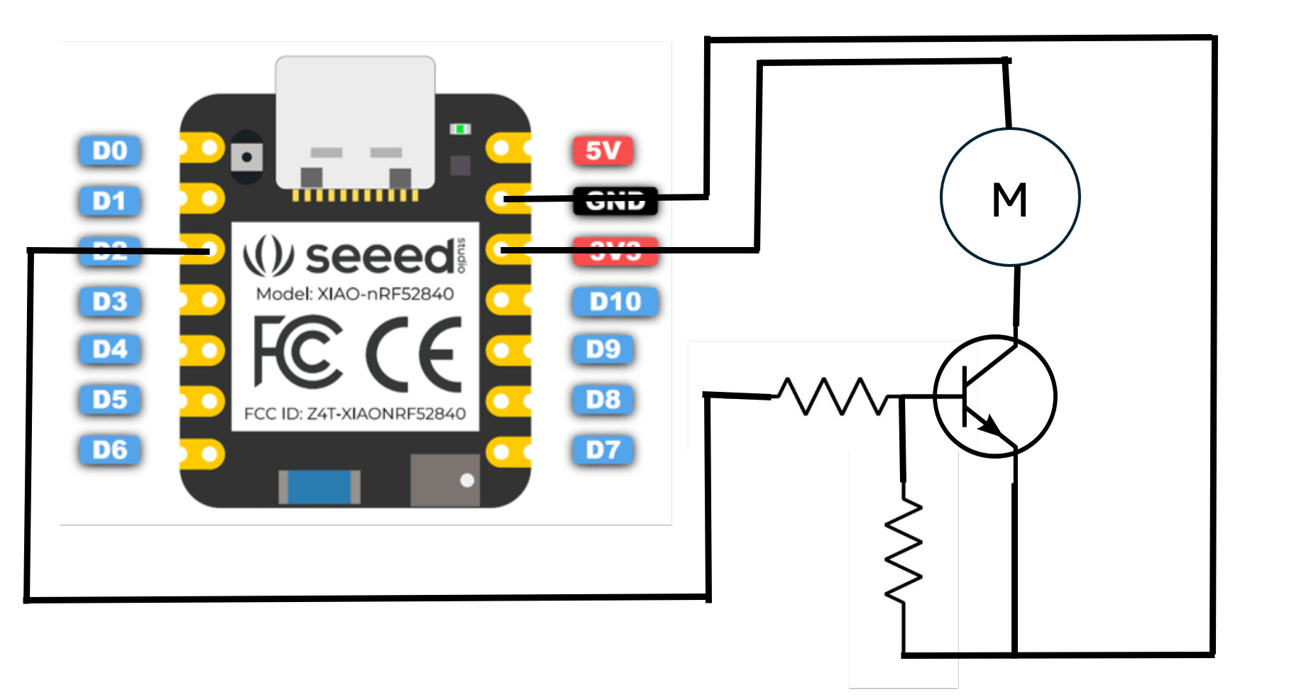
I have also tried adding a 2nd transistor so that Vcc will drive the base of the transistor that drives the motor, as shown below, but this also did not work on the Xiao Sense:
Thanks for any help @msfujino !
In your diagram, please give me the pin names of VCC, GND, PIN11, and PIN2 specifically in the Feather and XIAO pinout diagrams.
Your diagram does not show it, but need a base resistor between the base and the output port. What is the name of the transistor you are using?
For example, the following circuit should work easily.
Hi there,
If I may, the motor Should be in the collector side of the transistor.
HTH
GL PJ
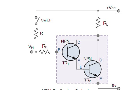
Look at this please.
I prefer a Darlington config for good drive current.
@msfujino Thanks for your patience and help
Transistor: 2N3904
Xiao Sense:
Vcc = 3V3
GND = GND
PIN 2 = P0.28 / D2 / A2
This is the PINOUT diagram from Seeed with the schematic as you described. Unfortunately, it still does not work with the P0.28 (what I called PIN 2) powering the base. Again, it works with 3V3 also connected to the base, so it seems a question of enough current being delivered
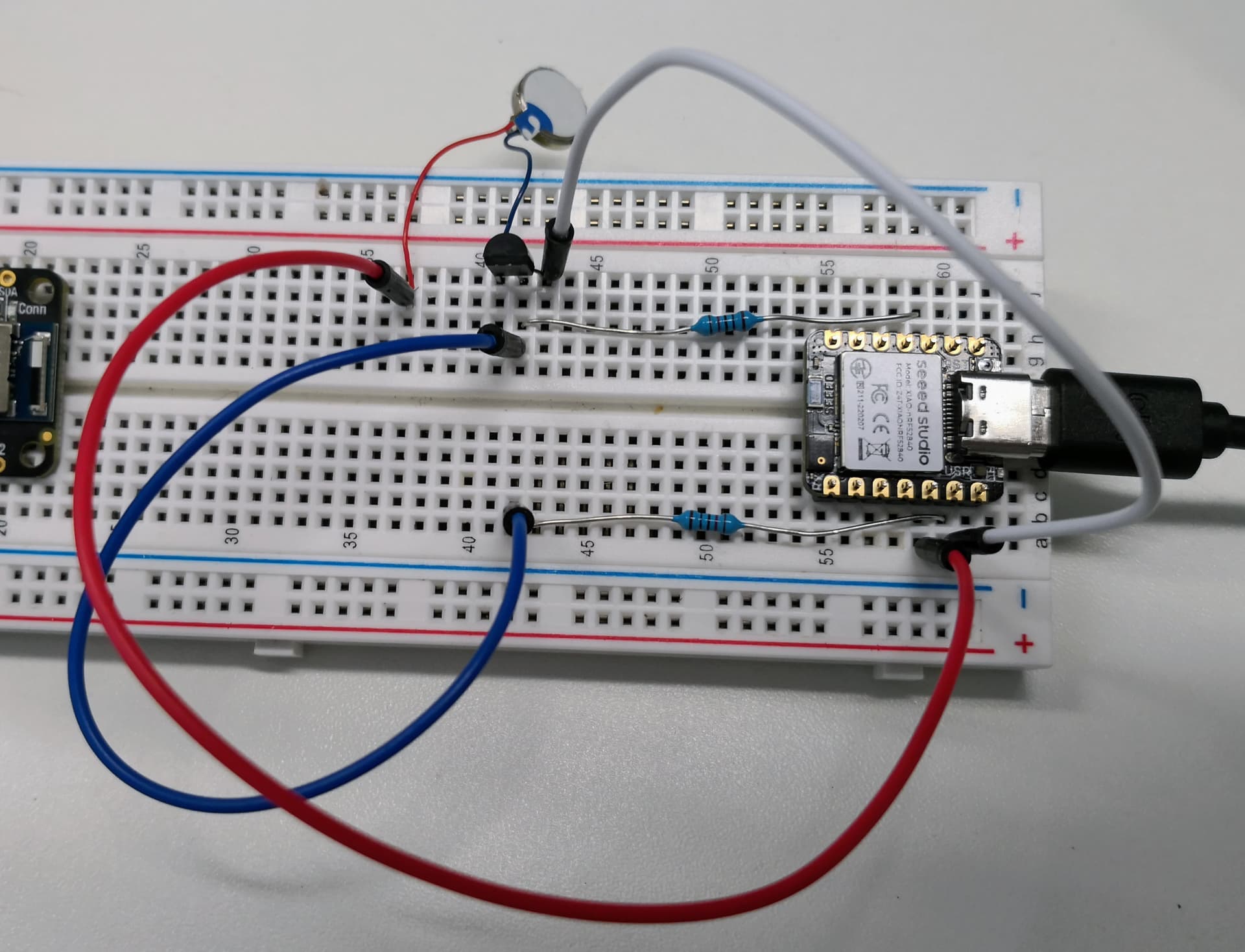
Here is an actual picture
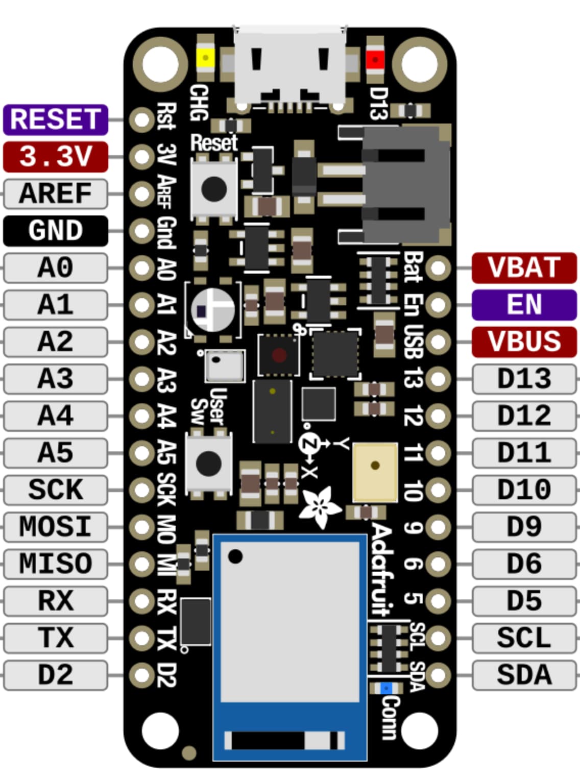
As for the Adafruit Feather Sense:
Vcc = 3V
GND = GND
PIN 11 = 11
These are the PIN names when looking at the board, as is also shown in this diagram:
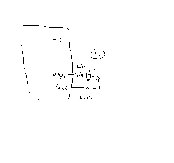
Partly solved!
I exchanged the 2N3094 Transistor with a 2N2222A, and it worked right away…
What is the reasoning for having the 10k Resistor between the Port and the Transistor Base, and another between the base to ground?
Hi there,
2N3904 200ma. Ic
2n2222 600ma. Ic
GL PJ
@PJ_Glasso The vibration disc does not use more than 85mA at 3.3V , so the Ic rating was not the issue. I think it must be the minimum Ib needed?
Hi there,
Perhaps, However that is the most obvious spec…diff between the two, I would have used an FET instead Anyway!
GL PJ
the main advantages of driving a motor with MOSFET is that an Input PWM signal can be used to smoothly control the speed of the motor is all I was getting at.
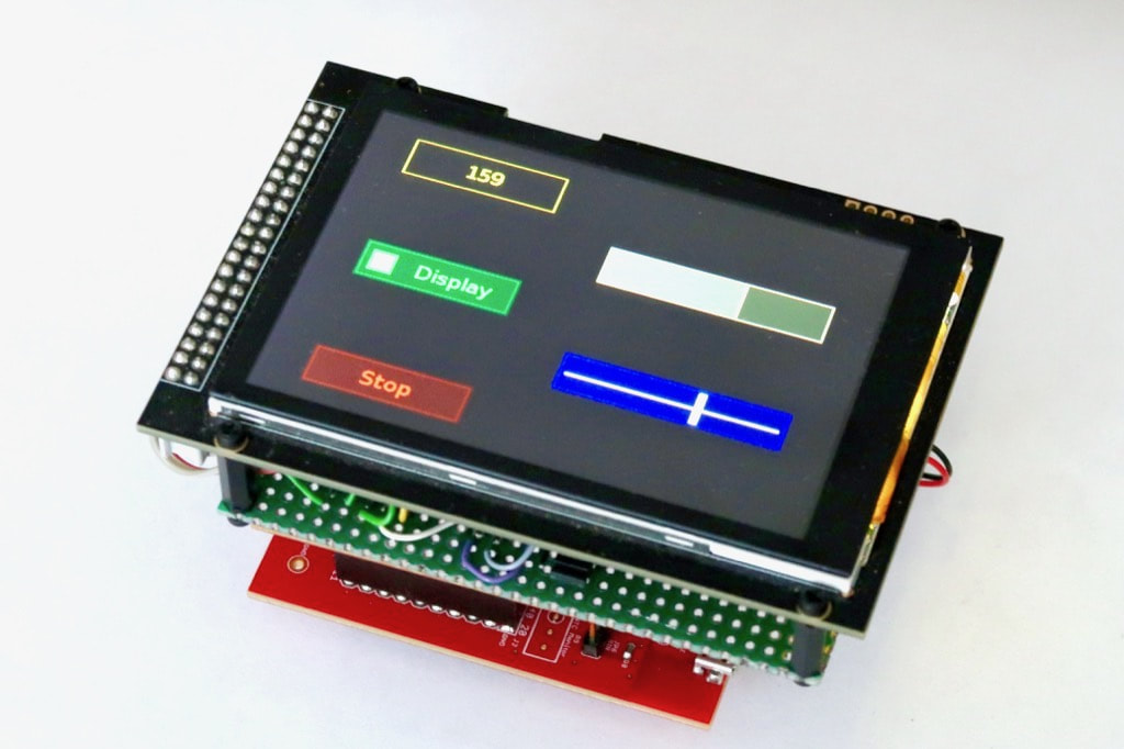
To drive a vibration motor, I recommend the excellent DRV2605 from Texas Instruments.
It connects through I²C bus and manages LRA and ERM. It features a library of vibrations for perfect haptic feedback.
I used it on my General purpose 3.5" screen with capacitive touch and haptic feedback.
The difference between 2N3904 and 2N2222A is the DC gain (ratio of base current to collector current): 30 for 2N3904 and 50 for 2N2222A.
This is not an exact calculation, but if an 85mA output is required, at least 3mA of base current must flow, and the base resistance must be reduced to about 1k. Without a resistor to limit the base current, a large base current may flow and damage the device.
The resistance between base and GND is used to quickly zero the base voltage.
It may also be necessary to connect a diode in parallel to the motor to prevent spike noise.
If you search for “transistor switching circuit” you will find the design method.
I think it is easier to design with FETs, though.
Hi there,
I agree 100%, I leave the Transistors for the Amplifiers, and use the MOSFET’s for the switching
plus with a pwm output you can vary the speed or vibration in this case. Unless it’s just ON/OFF.
but even better for a FET,Less battery too!
my .02
GL PJ