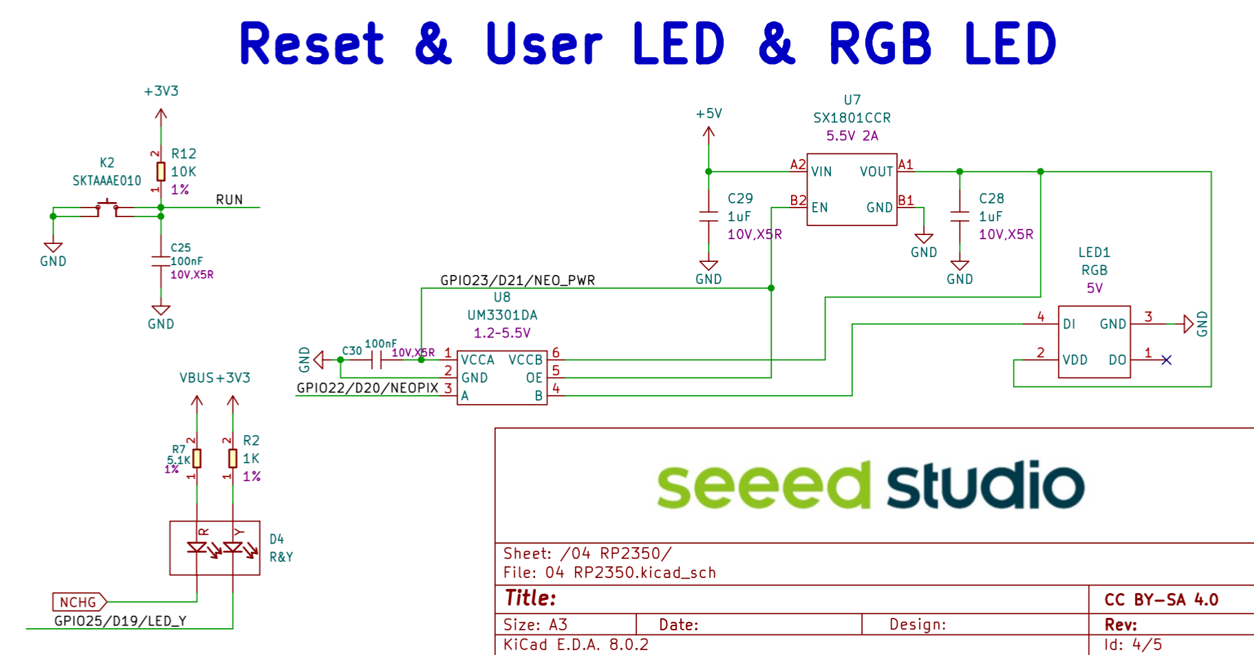
According to the schematic and the pcb, the XIAO RP2350 has a RGB LED.
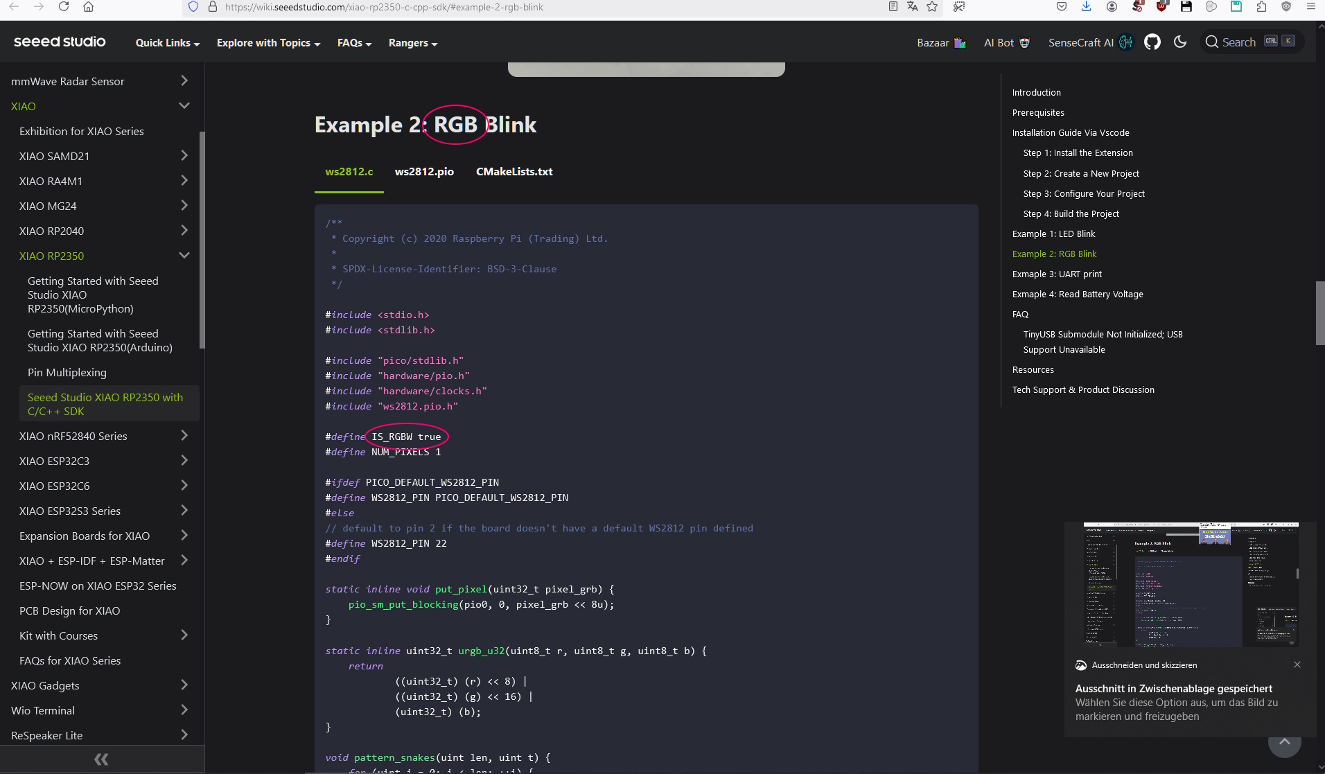
But in the RGB Blink example code there is a line #define IS_RGBW true.
This seems like a contradiction.
Does anybody know, why it’s not #define IS_RGBW false?
Maybe the RGB LED forgives the extra 8 bits without pause, but the code is still misleading.
I don’t own a XIAO RP2350 yet, so I can’t test.
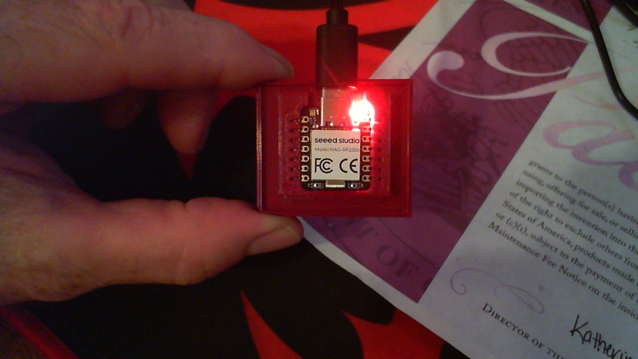
So They sent me one of these and I thought to check it out.
First you will need SUN GLASSES
This thing is BRIGHT. So looking at the Schematic you see the signal goes thru a 1-Bit Bidirectional Voltage level Translator UM3301DA, NO inversion takes place.
Well I got WHite SO Bright you need to wear SHADES…
Try this does it run ?
#include <Adafruit_NeoPixel.h>

#define LED_PIN   12     // GPIO12 (D12) controls the onboard WS2812
#define NUM_LEDS  1

Adafruit_NeoPixel led(NUM_LEDS, LED_PIN, NEO_GRB + NEO_KHZ800);

void setup() {
  led.begin();          // Initialize the LED strip
  led.show();           // Turn off all LEDs initially
}

void loop() {
  // Red
  led.setPixelColor(0, led.Color(255, 0, 0));
  led.show();
  delay(1000);

  // Green
  led.setPixelColor(0, led.Color(0, 255, 0));
  led.show();
  delay(1000);

  // Blue
  led.setPixelColor(0, led.Color(0, 0, 255));
  led.show();
  delay(1000);

  // White
  led.setPixelColor(0, led.Color(255, 255, 255));
  led.show();
  delay(1000);
}
LMK
GL PJ
note: and yes, the onboard WS2812B LED is still controlled via GPIO 12, just like on the standard RP2040 version. the Seeed XIAO RP2040 has a built-in WS2812B RGB LED (usually on pin D12 / GPIO 12), and you can control it using the Adafruit_NeoPixel library.
Chart on WiKi:
2340 1 user LED(3 colors), 1 power LED, 1 RGB LED
2350 1 user LED, 1 charge LED(Battery Charging Indicator),1 RGB LED
A RGB-LED has red, green and blue, so 3 leds in one.
A RGBW-LED has red, green, blue and white, so 4 leds in one.
And sure you can let a RGB-LED shine white, but that does not make it a RGBW-LED.
upload://bAe0XRlViOLIXWFuszuGx20mzOd.jpeg
Unfortunately the forum doesn’t let me post links or pictures.

