![]() Merry christmas to all my Fellow Technologists…
Merry christmas to all my Fellow Technologists… ![]()

I received a surprise in the post from those Awesome Seeed Imagineers. This time they made good on the promise to Designing and building ON livestream in REALTIME… to show users and makers that Seeed has the vision & bringing the receipts ![]()
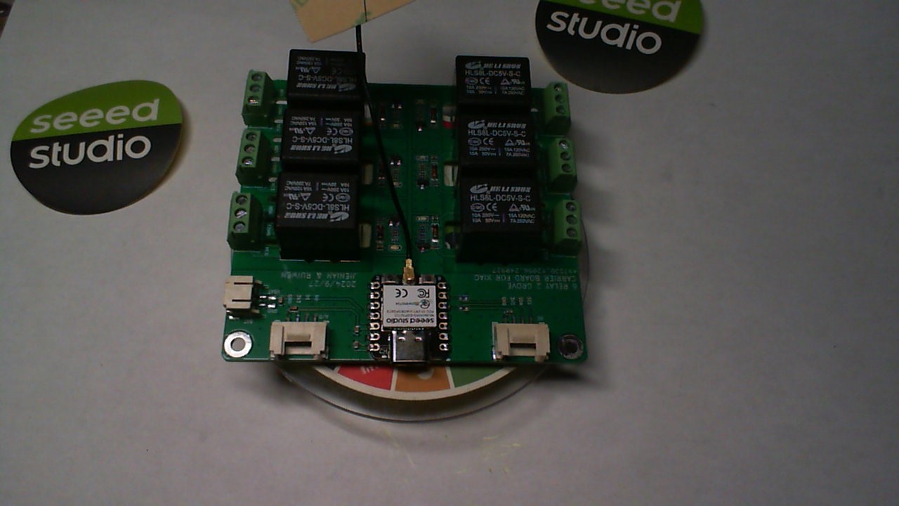
This unit is robust. My only add’s would be the Socket for a Xiao of your choice,based on power, budget, and features required for your topology. I can see a Matter controlled or Zigbee HA relay bank. Very Cool. It needs a power switch also.
It comes preloaded with a cycle relay “on” and “off” round robin code on it. (red leds) on each channel indicate relay status.
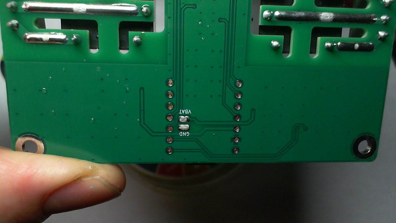
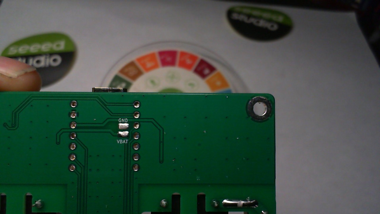
After checking it out and observing how well they followed my Tech on soldering the Battery pads on th PCB by adding the oval plated holes. Looks Tight!
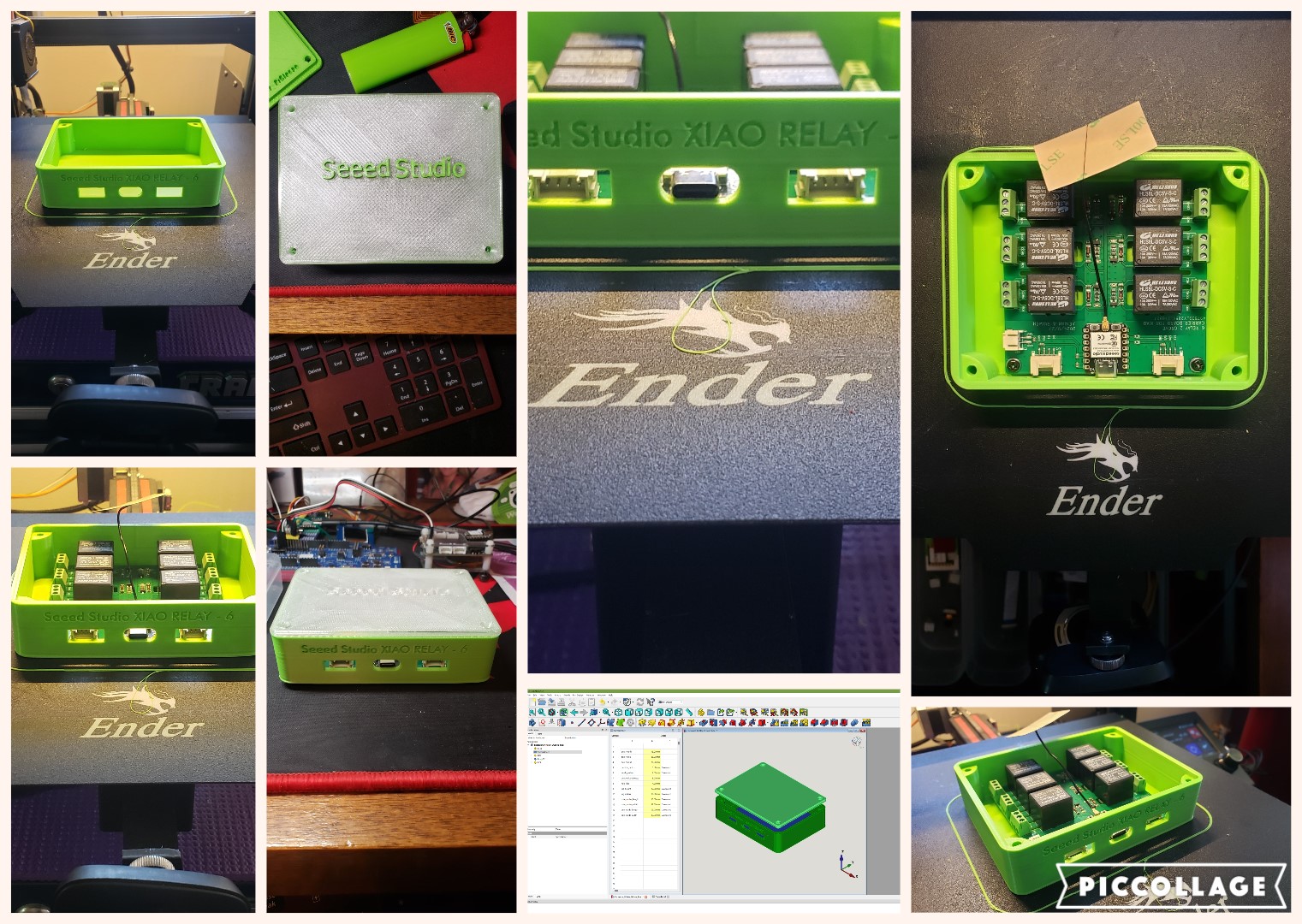
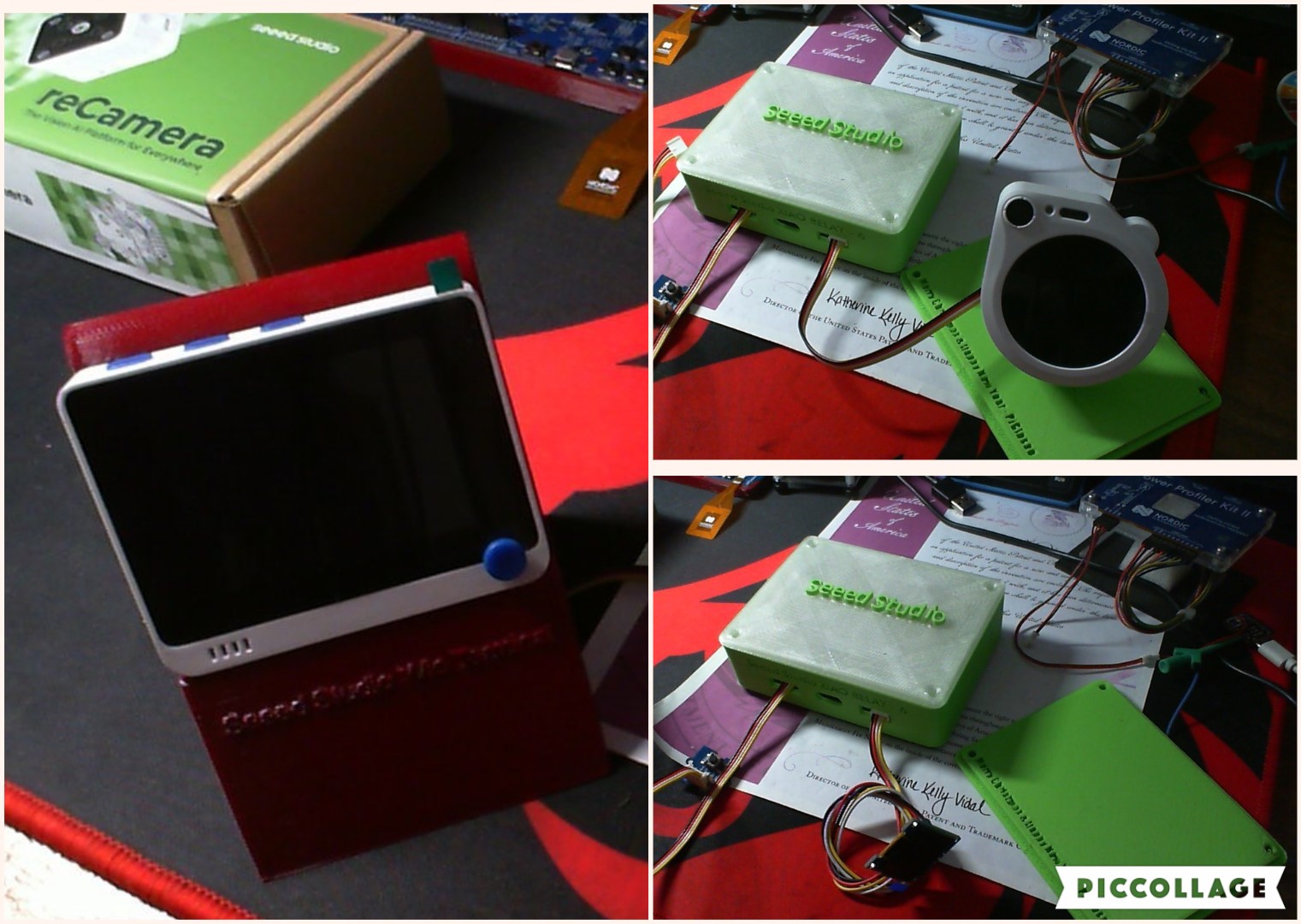
So I wasn’t about to just live vicariously through their efforts, so I figured an Enclosure was in order and would be my give back to the community and get a grip on making a parametric enclosure in FreeCad for Christmas. ![]()
a Parametric model is this:
Parametric modeling is a computer-aided design (CAD) technique that uses parameters, constraints, and relationships to create 3D models. It’s used in many fields, including engineering, architecture, product design, and aerospace.
Here are some key features of parametric modeling:
- Parameters
Adjustable variables that define the model’s geometry, such as dimensions, constraints, formulas, and material properties.
- Relationships and constraints
Define the behavior of the model’s geometry when changes are made.
- Design intent
Parametric modeling ensures that the model maintains its intended behavior when modifications are made.
- Automation
Parametric modeling automates much of the design process, allowing users to automate repetitive changes. Parametric modeling is different from direct modeling, where the designer manually creates shapes.
But in a NUTSHELL… it uses a spreadsheet to determine the dimensions , So you can change the basic L,W & H in the spreadsheet and then have a box for any size.(you can add your own hole locations easy.)
The video has some screen shots of it open in FreeCad.
I have added a Zip file with the FreeCad files and the 3D printer .STL files for the Xiao RELAY-6 enclosure. New users can learn FreeCad in an hour.
These are some Links to very good How to basics, easy enough a 3rd grader could do it. The Final Release candidate Version 1.0 is really Great!
I can’t believe it’s free. ![]()
I also went a tad over and made a custom LID with Inlaid letters (WIP) albeit the stock lid is perfect too! Seeed needs to sell the Sweet Green PLA+ I bought 3 rolls. Its a Unique Hue of Green not Fluorescent but a Satin Gloss , Even BIC lighter loves the Shade ![]()
I see this with the watcher controlling it or even the Wio Terminal anything with a Gove port is possible. a WiFi connected web page controlled relay bank or just a Display and a push button for local control works too. This is the closest to a multi-tool of relay banks.
This PCB has a Xiao ESP32C3 in it currently but any Xiao should make it go…
It powers up with USB also, and has a JST battery connector on board. Works on Battery power very well. Add your own Holes for cables. ![]()
Everyone is gonna want one of these if the price is right ![]() . HA is gonna love this thing.
. HA is gonna love this thing.
Probably the BEST Tech Christmas gift soFar from Seeed Studio. (the reCamera) close 2nd ![]()
GL ![]() PJ
PJ ![]()
Merry Christmass to all and to all a Good night! ![]()
Enclosure_6Relay_2Grove_box-Body_lid.zip (2.1 MB)