Hello all. I just bought a Xiao RA4M1 and want to try its CAN network capabilities. The official documentation Getting Started with Seeed Studio XIAO RA4M1 | Seeed Studio Wiki does not touch on it.
Will an Arduino CAN library https://lastminuteengineers.com/esp32-can-bus-tutorial/ work for the Xiao RA4M1?
Hi there,
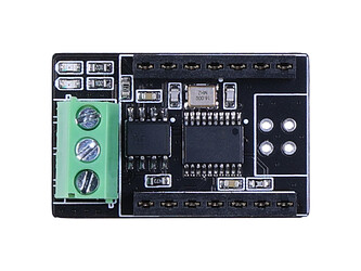
So You must have missed it but in the next section APPs I believe, there is most definetly a great set of CAN topics. and it plugs right in to this.
HTH
GL  PJ
PJ 
I prefer the socket…LOL

2 Likes
I believe that the other “pin multiplexing” page you mentioned with an example CAN setup is using the SPI interface on the RA4M1 along with the MCP2515 controller on the extra breakout board. Is that correct?
I am looking for information on how to use the native CAN RX/TX pins that are built-in to the RA4M1. I think it should be able to connect directly to a transceiver chip without the extra controller chip required. I suspect that @clovisf may also have originally been thinking of that when posing the first question. Since one of the listed features of the RA4M1 vs many other boards is native CAN BUS support.
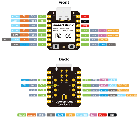
It is also unclear which pins are actually the CAN RX/TX pins. On the “front” side pinout of the “getting started” page, it shows D9 as CRX0 and D10 as CTX0. And on the “back” side pinout, it shows D17 as CRX0 and D18 as CTX0. I don’t think they are in two places so I think there may be an issue in the pinout doc.
Thanks for any additional information you might have.
1 Like
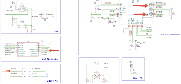
Thanks for your inquiry. For the second question, I confirmed that D9 and D17 are both CRX0. Let’s check the XIAO RA4M1 pinout sheet, XIAO RA4M1 schematic and RA4M1 chip datasheet together:
——————————
In XIAO RA4M1 pinout sheet, D9 = P110 = CRX0, D17 = P102 = CRX0.
——————————
In XIAO RA4M1 schematic, (Position of) D9 = P110, (Position of) D17 = P102. Please notice that the 8 pins on the backside is horizontally reversed in the schematic because everything on it are looked from the same direction.
——————————
https://www.renesas.com/en/document/dst/ra4m1-group-datasheet
In RA4M1 chip datasheet, we can see that P110 and P102 are indeed CRX0.
1 Like
Thank you very much for helping me understand that the CTX0/CRX0 can come out to two locations as the pinout showed. I didn’t study the schematic and datasheet enough and your explanation helps a lot.
How do I select which one is going to be used? Any code examples would be really helpful.
