I’ve just came across an interesting topic. Speaking in general about nrf52840, I understand that the chip accepts 1.7V-5.5V to work correctly, and that it is possible to set the output voltage of GPIO, namely Vlogic, to different values, like 1.8V, 2.4V, 3.3V, etc. as per this doc:
In my system I have ICs working with 2.4-2.5V logic level and right now I use a logic level translator IC to convert 3.3V logic of XIAO to 2.5V logic of my ICs. Hence, removing an extra IC looks like a great thing, if it is possible to program XIAO into being able to output 2.5V logic, rather than 3.3V.
So, I have the following questions I would like you to help me confirm:
In a final device, where I will use an nrf module (or even a raw chip), I understand it correct, that I can power the chip up with the 5V and achieve the GPIO logic output as 2.5V via the register change?
Is it possible to “flash” XIAO nrf52430 now to output 2.5V from the GPIOs? Did anyone try it? I believe it is only possible via the J-Link, right?
Although I haven’t tried it but know of Hardware that has this enabled for a (EWEElink door sensor with CR battery). It breaks down like this.
The nRF52840 can operate at different logic levels because its GPIO voltage levels are tied to the VDD supply voltage. You can configure the GPIO voltage level dynamically by adjusting VDD and, in some cases, by using the programmable power supply output (VDDH).
nRF52840 GPIO Logic Levels Overview
Default GPIO Logic Level (VDD Mode)
The GPIO logic level is directly tied to the VDD supply voltage.
Example: If VDD = 3.3V, GPIO high logic (1) is 3.3V.
If VDD = 1.8V, GPIO high logic (1) is 1.8V.
This allows the nRF52840 to be compatible with different voltage domains (1.8V, 3.0V, 3.3V).
High Voltage Mode (VDDH Mode)
The nRF52840 has a high-voltage regulator that allows it to run from a higher supply voltage (up to 5.5V).
This is controlled using the REGOUT0 register.
It allows you to configure VDD to 1.8V, 2.1V, 2.4V, or 3.0V.
Programmable Output Voltage
When powered from VDDH (e.g., 5V input), you can configure the REGOUT0 register to select a lower regulated VDD output.
This affects the GPIO logic level accordingly.
How to Configure GPIO Logic Levels on nRF52840
1. Set VDD Voltage (Hardware)
Direct Connection: If you power the nRF52840 at 3.3V, GPIO high logic (1) will also be 3.3V.
Low-Power Mode: If powered at 1.8V, GPIO outputs are at 1.8V.
2. Configure REGOUT0 for VDDH Mode (Software)
If you’re using VDDH (e.g., powered from USB 5V), you can configure REGOUT0 to select a different logic level.
#include <nrfx.h>

void configure_voltage_output() {
    if (NRF_UICR->REGOUT0 == 0xFFFFFFFF) {  // Check if default value (unset)
        NRF_NVMC->CONFIG = NVMC_CONFIG_WEN_Wen;  // Enable writing to UICR
        while (NRF_NVMC->READY == NVMC_READY_READY_Busy);

        NRF_UICR->REGOUT0 = UICR_REGOUT0_VOUT_3V0;  // Set VDD to 3.0V
        NRF_NVMC->CONFIG = NVMC_CONFIG_WEN_Ren;  // Disable writing to UICR

        NVIC_SystemReset();  // Reset for changes to take effect
    }
}
Voltage Options (REGOUT0)
UICR_REGOUT0_VOUT_1V8 → 1.8V
UICR_REGOUT0_VOUT_2V1 → 2.1V
UICR_REGOUT0_VOUT_2V4 → 2.4V
UICR_REGOUT0_VOUT_3V0 → 3.0V
Important Notes:
* You must reset the chip after writing to REGOUT0 for changes to apply.
This only works when powered from VDDH (e.g., USB 5V).
When Would You Use This?
Interfacing with Different Voltage Logic
If connecting to a 1.8V sensor, set VDD = 1.8V to match logic levels.
If connecting to a 3.3V peripheral, set VDD = 3.3V.
Low-Power Optimization
Lowering VDD to 1.8V reduces power consumption.
Using USB Power (5V)
If running from USB (5V, VDDH mode), you can set VDD = 3.0V using REGOUT0.
Summary
GPIO voltage levels depend on VDD (1.8V to 3.3V). Using VDDH (5V) allows programmable voltage output (REGOUT0). To change voltage in software, configure REGOUT0 and reset the device.
No way! I really thought this is something which needs a bootloader change or a debugger in place. Never realised it can be done simply via the code. I’ll try to run it on XIAO today. I hope there’s nothing on top of the vanilla nrf GPIO on this board. As I understand it needs to be done once only, and then the change is in the NVM (unless I erase it in future).
While this, I believe, is something not possible with XIAO, since it has its own power schematics, correct? But on the vanilla nrf82540 I can supply 2.5V to the chip and have the 2.5V logic, without the need to do the software changes?
Also, a question: when it is said, that nrf52840 accepts 1.7v-5.5v power supply, it means it should be constant, correct? I can’t power it with, let’s say 2 AA batteries providing 3.0V and then, the battery will slowly discharge but the chip will be working until the battery is at 1.7V level. And even if it can work this way, the GPIO output won’t stay at 2.5 all the time of course.
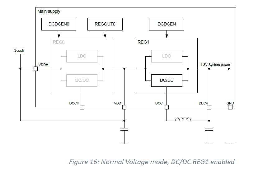
According to the schematic of XIAO_nRF52840, VDDH and VDD are connected and an inductor is connected to DCC and DEC4.
This corresponds to “5.3.1.4 Regulator configuration examples Figure 16: Normal Voltage mode, DC/DC REG1 enabled” in the datasheet,
The VDD voltage cannot be changed with the REGOUT0 register.
When designing a new circuit, use “Figure 17: High Voltage mode, LDO only” or “Figure 18: High Voltage mode, DC/DC for REG0 and REG1 enabled”, the voltage on the Supply pin can be stepped down to the REGOUT0 register setting, and a low voltage can be output as VDD.
Yes , See the Gotcha , @msfujino is pointing out. You See I can configure the nRF52840 DK to use different GPIO logic levels using the REGOUT0 register, However, there are some differences because the nRF52840 DK has built-in power regulators and selectable supply sources.
HTH
GL PJ
You could maybe get some custom Xiao from Seeed Fusion Service without the LDO setup ?
I’ve found that topic in the nrf52840 datasheet and read through it.
I think, that in the final design I may also go with the Normal mode, but I just power-up the chip with 2.5V. Hence, I’ll have GPIO level at 2.5V as well. Most probably this is the easiest scenario. As I understand, in this case I can go with the LDO, as the power saving with using DC-DC converter will be neglectible.
In contrary, if I decide to power up the chip with 5V, then I have to go for the Regout0 option to step down the voltage to 2.5V an use the DC-DC converter, since the difference between Vin and GPIO voltage is drastic.
However, since my system is 2.5V compatible, I believe the option to select is evident.
As I understand, this is also something I can’t experiment with XIAO, as it expects 5V in its Vin, and then 3.3V are hard-wired to VDD and VDDH, according to this:
The DK is ordered, so, hopefully, I’ll be able to experiment with this soon.
As I has also ordered a Dongle, based on the description, this feature is also available there, so I can right away test it in my project in a size-friendly way. @PJ_Glasso , thanks a lot for pushing me onto this territory!
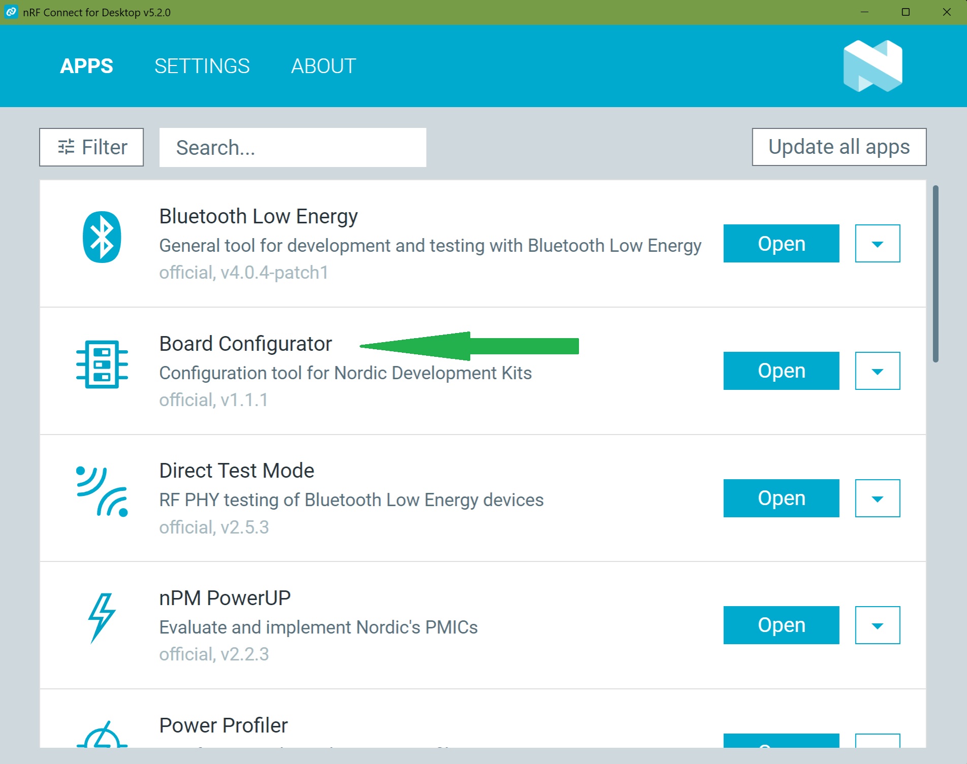
Is it something which can be selected via the nrf Desktop application?
P.S. I was able to find an answer to my stupid question about skipping any buck/boost converters and recklessly supplying a ranged voltage over the period of the battery life directly to the nrf52840, namely: whatever the battery gives out until it hits as low as 1.7V.
Minimum voltage drop in REG0 (difference between voltage supplied on VDDH pin and voltage output on VDD pin) - 0.3V
Hey, guys! Long time no talk. I was finally able to get back to the project.
My set up is nrf52840DK and nrf PPK2 in Source mode outputing 2.25V.
My goal is to:
Power the nrf52840 chip with 2.25V
Have nrf52840 logic HIGH as 2.25V
Have the nrf52840DK be connected to the USB for reading the console
I’ve connected PPK2 to the external supply port of the nrf52840DK (V out to +, GND to -). When the nrf52840DK is not connected to the computer via the USB I see 2.25V as logic HIGH from my GPIOs. However, when nrf52840DK is connected to the computer via USB for reading the console, I see, that nrf52840DK outputs 3V as logic HIGH.
Is there a way to achieve the 2.25V as a VDD of the chip and still have the USB connected without getting into the settings programmatically and setting up the voltage there?
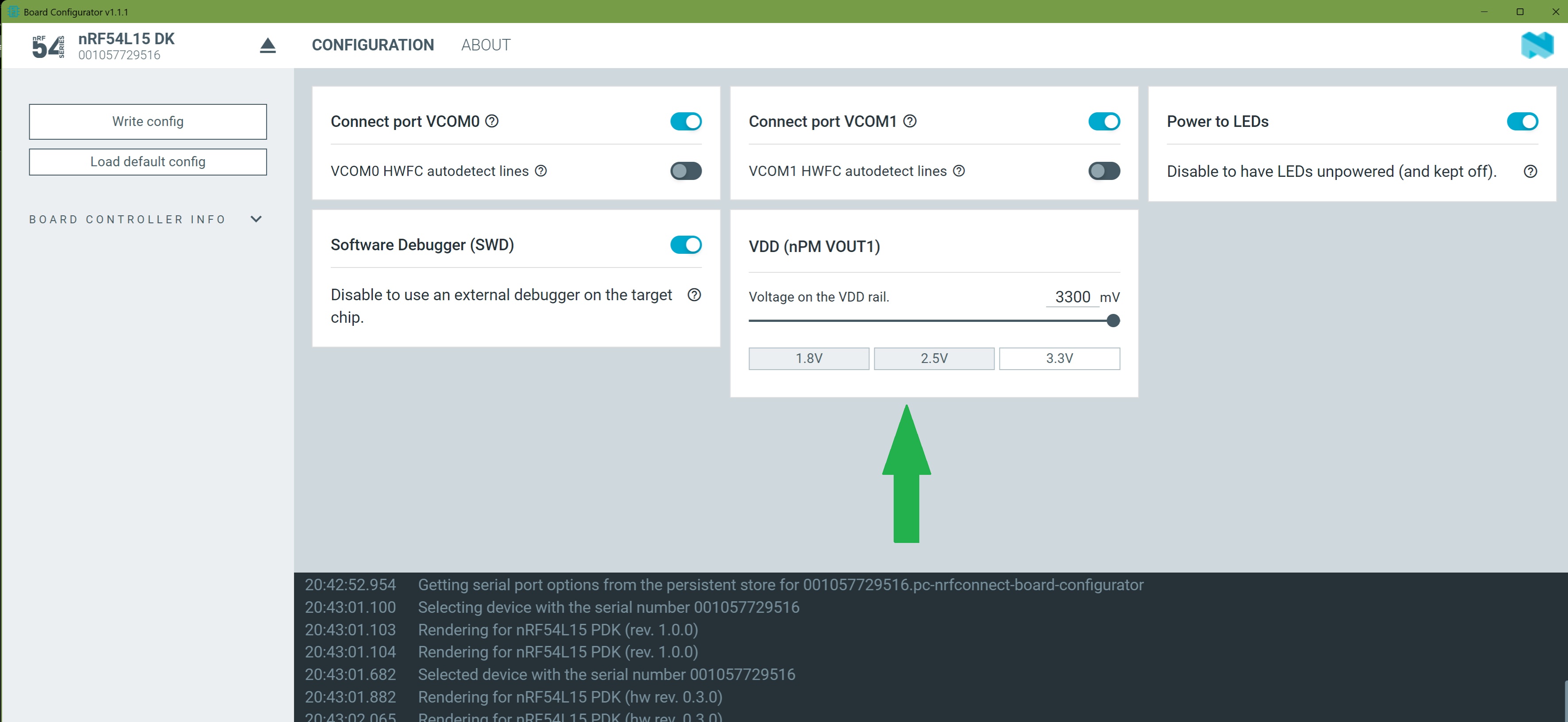
So, I think you may have jumpers,(solder bridges) to do it, On the Newer DK’s the Board configurator Sets the nRf54L15 VDD operating level. in the nrf_connect for Desktop.