Hi folks, i had a project a while back using esp32c3 (exchanged for c6 to get it working properly) that was essentially a wireless temperature sensor that transmitted data to a raspberry pi. I’m trying to recreate the same but using LoRa instead and i’m really struggling to get anywhere whatsoever (much like when i started the last project).
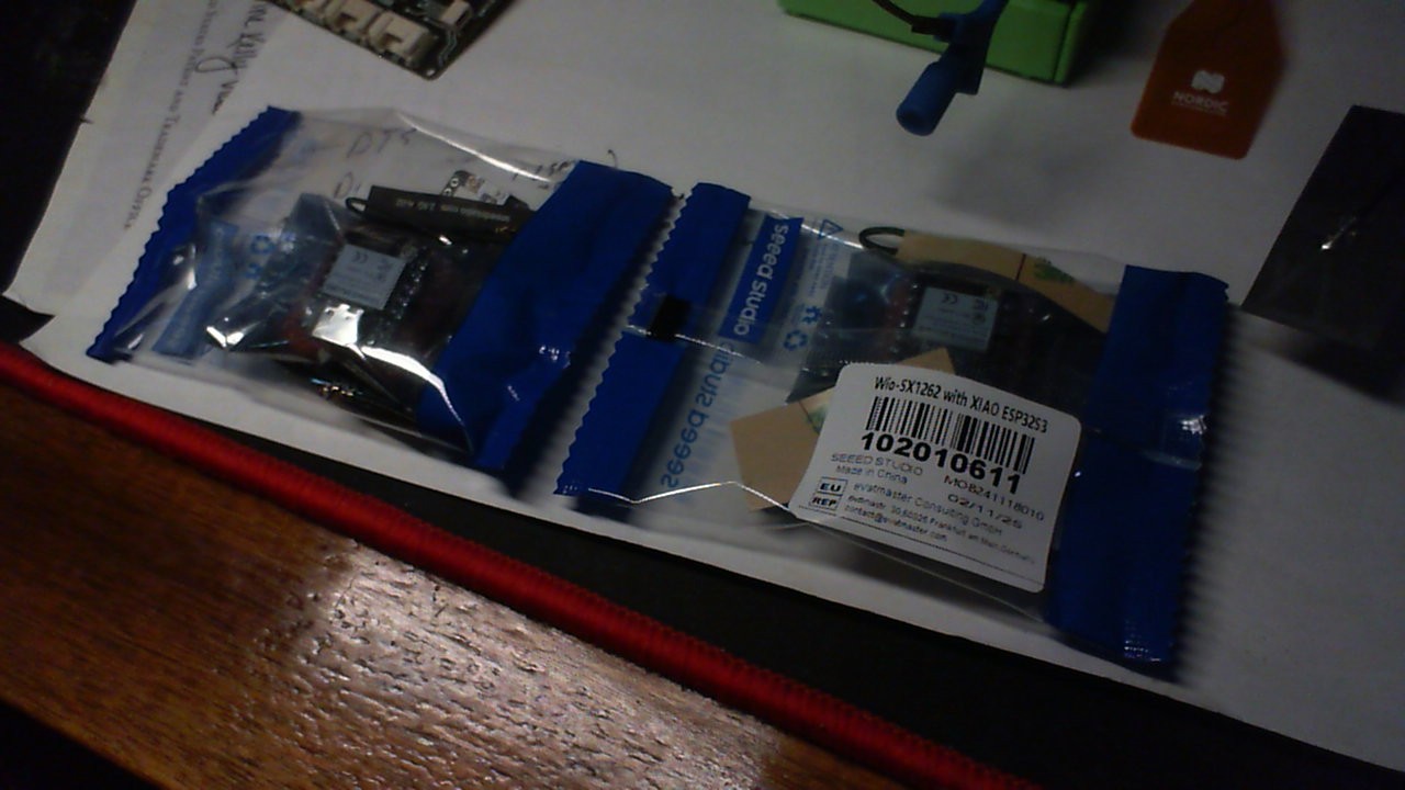
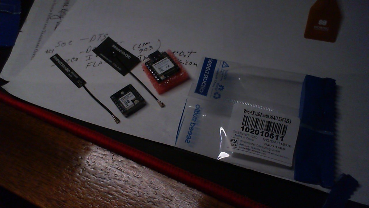
I’ve got a waveshare sx1262 LoRa hat connected to the raspberry pi and I think it’s possibly working but I can’t send anything to test it yet as I’m getting no-where with the esp32s3/wio-sx1262 kit. I’ve been trying to track down the correct SPI pin numbers and have looked at schematics etc but I’m still just getting my “it’s not working” errors when running my sketch.
I’ve tried some basic SPI tests that ChatGPT came up with as well and getting errors when trying to test SPI.
I’ve fed it everything I could find schematics/github repos/tutorials wise in my usual project start of smash all the info into AI then wade through the nonsense to piece together something sensible but it’s not going well.
Can anyone point my in the right direction please?
Sketch is currently:
#include <SPI.h>
#include <OneWire.h>
#include <DallasTemperature.h>
#include <RadioLib.h>

// Device Configuration
#define DEVICE_HOSTNAME "RevTmp-3"
#define ONE_WIRE_PIN 2   // DS18B20 data pin
#define BATTERY_PIN 4    // ADC pin for battery voltage

// LoRa Configuration (B2B Connector Pin Mapping)
#define LORA_NSS 17    // SPI Chip Select
#define LORA_RST 18    // LoRa Reset
#define LORA_BUSY 14   // LoRa Busy Pin
#define LORA_DIO1 16   // LoRa DIO1 (IRQ)
#define LORA_MOSI 47   // SPI MOSI
#define LORA_MISO 48   // SPI MISO
#define LORA_SCK 21    // SPI Clock

// LoRa Parameters
#define LORA_FREQUENCY 868E6   // Ensure the correct frequency for EU
#define LORA_SPREADING_FACTOR 12  // SF12 for long range
#define LORA_BANDWIDTH 125E3   // Bandwidth: 125kHz
#define LORA_CODING_RATE 5     // Coding rate 4/5
#define LORA_TX_POWER 22       // Transmission power in dBm

// OneWire for Temperature Sensor
OneWire oneWire(ONE_WIRE_PIN);
DallasTemperature sensors(&oneWire);

// LoRa Module Instance
Module mod(LORA_NSS, LORA_DIO1, LORA_RST, LORA_BUSY);
SX1262 radio(&mod);

void setup() {
    Serial.begin(115200);
    Serial.println("Starting ESP32S3 Pro...");

    // Initialize Temperature Sensor
    sensors.begin();

    // Initialize SPI Bus
    Serial.println("Initializing SPI...");
    SPI.begin(LORA_SCK, LORA_MISO, LORA_MOSI, LORA_NSS);

    // Perform a manual reset on Wio-SX1262
    Serial.println("Resetting LoRa module...");
    pinMode(LORA_RST, OUTPUT);
    digitalWrite(LORA_RST, LOW);
    delay(10);
    digitalWrite(LORA_RST, HIGH);
    delay(10);

    // Initialize LoRa
    Serial.println("Initializing LoRa...");
    int state = radio.begin();
    Serial.print("LoRa Init Status: ");
    Serial.println(state);

    if (state == RADIOLIB_ERR_NONE) {
        Serial.println("✅ LoRa initialized successfully!");
    } else {
        Serial.println("❌ LoRa initialization failed!");
        Serial.print("🔎 Error Code: ");
        Serial.println(state);
        Serial.println("📌 Possible Causes:");
        Serial.println("- Incorrect SPI pin mappings");
        Serial.println("- B2B connector not fully inserted");
        Serial.println("- Insufficient power to Wio-SX1262");
        Serial.println("- SPI bus not working correctly");
        while (true);
    }

    // Ensure we are in raw LoRa mode
    radio.setFrequency(LORA_FREQUENCY);
    radio.setSpreadingFactor(LORA_SPREADING_FACTOR);
    radio.setBandwidth(LORA_BANDWIDTH);
    radio.setCodingRate(LORA_CODING_RATE);
    radio.setOutputPower(LORA_TX_POWER);

    // Gather Sensor Data
    float temperature = readTemperature();
    int batteryPercentage = getBatteryPercentage(readBatteryVoltage());

    // Construct JSON message
    char message[128];
    snprintf(message, sizeof(message),
             "{\"hostname\":\"%s\", \"temp\":%.2f, \"batt\":%d}",
             DEVICE_HOSTNAME, temperature, batteryPercentage);

    Serial.print("Sending LoRa Message: ");
    Serial.println(message);

    int status = radio.transmit(message);
    if (status == RADIOLIB_ERR_NONE) {
        Serial.println("Message sent successfully!");
    } else {
        Serial.printf("LoRa transmit failed, code: %d\n", status);
    }

    Serial.println("Entering deep sleep for 15 minutes...");
    delay(100);
    esp_sleep_enable_timer_wakeup(15 * 60 * 1000000ULL);
    esp_deep_sleep_start();
}

void loop() {}

// Read Temperature using OneWire & DallasTemperature
float readTemperature() {
    sensors.requestTemperatures();
    float temp = sensors.getTempCByIndex(0);
    Serial.printf("Temperature: %.2f°C\n", temp);
    return temp;
}

// Read Battery Voltage using 220KΩ / 100KΩ Voltage Divider (16-sample averaging)
int readBatteryVoltage() {
    long sum = 0;
    for (int i = 0; i < 16; i++) {
        sum += analogReadMilliVolts(BATTERY_PIN);
        delay(5);
    }
    float measuredMilliVolts = sum / 16.0;
    int batteryMilliVolts = measuredMilliVolts * 3.2;
    Serial.printf("Battery Voltage: %dmV\n", batteryMilliVolts);
    return batteryMilliVolts;
}

// Convert Battery Voltage to Percentage
int getBatteryPercentage(int batteryMilliVolts) {
    int fullCharge = 4200;
    int emptyCharge = 3200;
    int batteryPercentage = ((batteryMilliVolts - emptyCharge) * 100) / (fullCharge - emptyCharge);
    return constrain(batteryPercentage, 0, 100);
}
I’m (very likely) just doing something inherently wrong. If anyone could push me in the right direction I’d likely be able to get through the leg work myself, just need to know where to head.
After scouring the internet for information i found several suggestions as to what the pins are through the b2b connector but still not getting anywhere, updated sketch below and some information links I’ve gathered:
So My set is in transit… But which BSP are you using to compile with? Have you tried the older ones?
You are very close , Looks like the INIt for Lora is failing? (mr obvious)
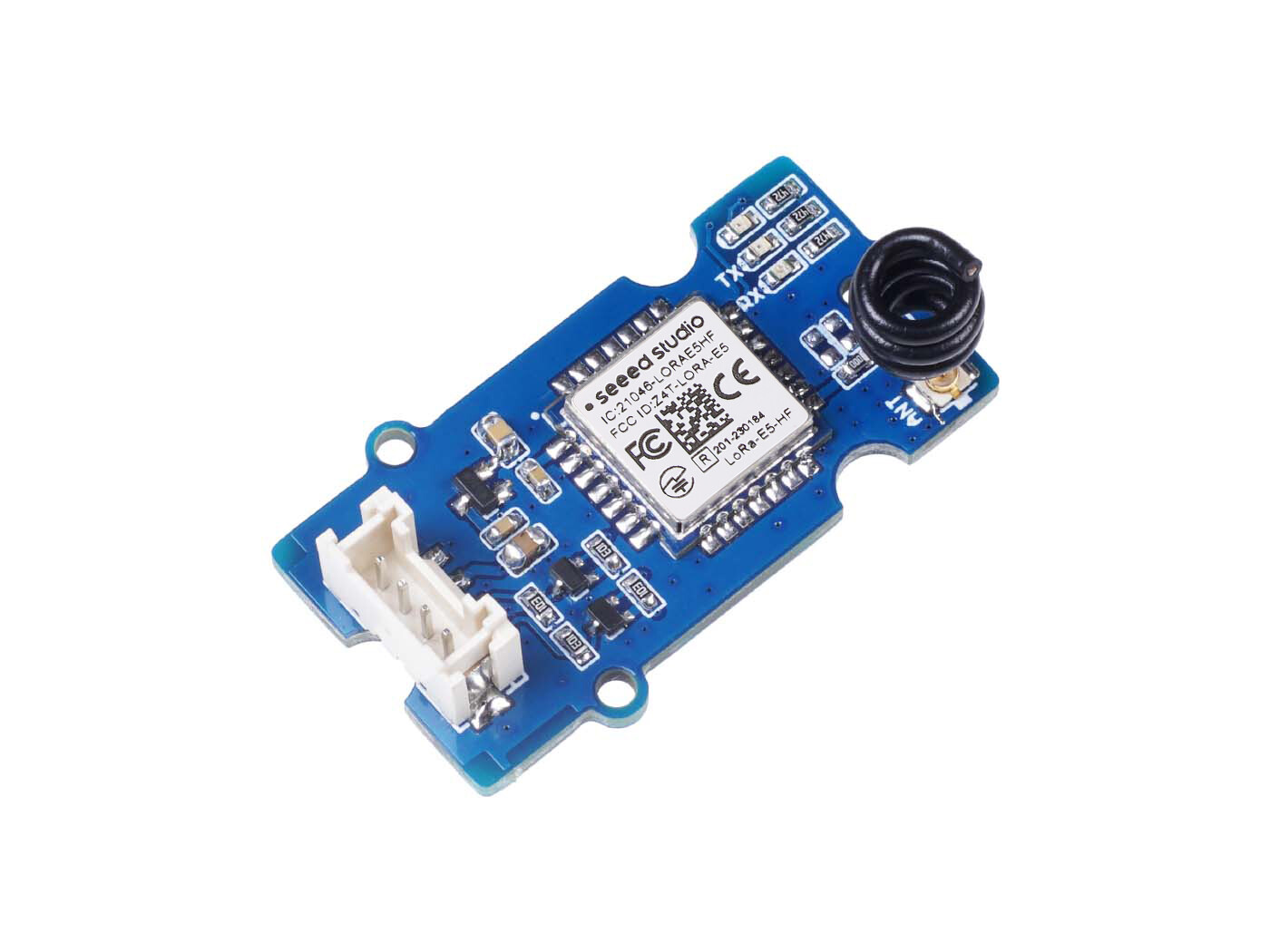
do you have any other LORA stuff? Grove Lora board maybe?
I think it needs a string or command with a CRC or something, is it communicating with the SX or NO?
Keep going maybe someone else can comment, but try rolling back the BSP and see if it improves?
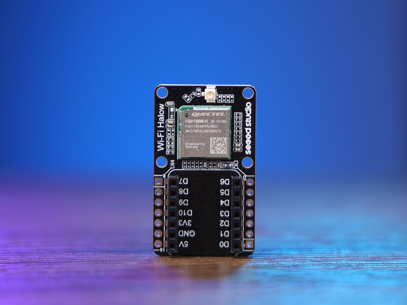
The Wi-Fi Halow Board based on the FGH100M-H module is a high-performance, long-range Wi-Fi HaLow solution. Operating in the 902-928 MHz frequency band, it offers excellent penetration and coverage, making it ideal for smart home and IoT applications. With its compact design and compatibility with the Seeed Studio XIAO ecosystem, this card ensures reliable and efficient connectivity for various projects.
Hi PJ, glad to hear from you! I was using 3.1.1 originally, came across your camera post and downgraded to 2.0.8 just cause it was a number you’d mentioned but still the same.
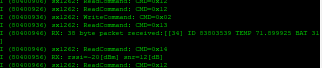
I can communicate through SPI and get correct responses form the 1262 but not able to use it to send any messages yet.
I’ve got a heap of LoRa stuff sitting here just now (challenger rp2040, helvec something lora 2 kit) which i might revert to for a while just to build up the experience and see if that helps at all with this.
Going by the struggle in setting this up just to send a message i’d be very surprised if the LoRa hat in my raspbery pi is actually working, it tells me it’s listening for messages but it could just be pretending since it knows I’ve no way of sending one yet.
The wifi project is working away quite happily getting perfect 15 minute readings from them even buried in a freezer far from the access points but with an rssi from -30 to -90 i’d rather switch it to LoRa if i can. Thanks again for your help with that.
I’ll have more on the Set when I receive them , should be any minute…
DOwn FOMO, DOwn…
I don’t do a lot with RPI’s they always seem to be too much or run out of Juice when things finally get rolling. Sometimes like killing a fly with a shotgun. lol
These S3 + Lora should be just right for a P2P with minimal fuss I be reporting back SOON.
I like an RPi as a mini server for things like this, that’s about it really…oh, and a pihole on my network.
I’m still none the wiser with this, still think I’m doing something fundamentally wrong (other than not having a clue).
Are there any simple sketches out there for these kits? One that just sends “hello world” and one that monitors and receives? I’ve come across a few but can’t get any to work and the instructions on the wiki seem to be only for meshtastic
Trying to bring it right back to basics and work from there but can’t even get started with that due to conflicting information and a lack of noise about them, unless I’m looking in the wrong place (entirely possible)
I’m assuming everyone else just managed to get this working because they knew what they were doing and that’s why I can’t find a definitive guide?
Tried to translate this into my hardware but I think my main issue is the pins are wrong, thought I’d narrowed them down but not sure now if it’s still the pins or my sketch or I’ve gone completely the wrong way and I’m just typing nonsense into my sketches
I just purchased 3 of the wio-wm6180 wifi halow boards, I also purchased 3 of the ESP32-C6 boards I was hoping to use together. I also have 1 of the ESP32-S3 & Wio-SX1262 combos for another project. I’m having issues setting up the ESP32-C6 boards on the halow boards. I’m on a linux mint machine, I was able to pop the ESP32-S3 onto the halow and flash / connect to it, but no luck with the ESP32-C6 yet. any guidance would be greatly appreciated. I’m trying to setup AP’s to connect my other wifi devices and projects around my property…
Another side question, if I do have to stack the ESP32-S3 on the HaLow board could I also stack the Wio-SX1262 on top of the S3 as well? now that would be an awesome stack! Very useful…
So the first part first , Which BSP are you using with it as Target ?
More than likely that may be the issue , what kind of problem do you get?
I see the WIKI also your ESP-IDF must be 5.1.1
AS far as the stacking thing, some success has happened, If you use the S3 with the B2B connector the SX1262, you probably could stack it into the HaLow board.
HTH
GL PJ
Also you may want to start a new thread on this… as this one is old.