I have 2 XIAO ESP32S3 & Wio-SX1262 kits for meshtastic and I want to sense an input. A switch easy if the switch is triggered send out a message. Its for trap line of cat traps we need to know as soon as a cat is caught.
I have the meshtastic firmware installed and the app sees the nodes.
How do you a the rest of the programming?
I meshtastic on a partition and I load a simple arduino code for my message trigger??
there must be examples could your point me in the right direction pls.
Hi there,
Oh’ hell no… LOL ![]()
it’s in the config settings anyway pick the Gpio and the notification, and RTFM for any extra’s ![]() poor cats…
poor cats… ![]()
HTH
GL ![]() PJ
PJ ![]()
If you are on the Seeed Discord… place this question on Smart-Citizen-Meshtastic… Discord
Thanks for the reply
where do I find the F**king manual ?
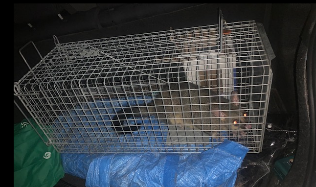
The cats get new homes away from sensitive wildlife in this case the last 10 breeding penguins in our town
Hi there,
Just messing with you ![]() , but yea, it’s the Wiki, the meshtastic one though
, but yea, it’s the Wiki, the meshtastic one though
you go in the settings and Pick a GPIO, and some other parms and it just works. I’ll look for the link and get back. same way you enable the display’s (3 types). but deeper
GL ![]() PJ
PJ ![]()
You may want to researcht this device Wio Tracker 1110 Dev Kit for Meshtastic
I think it was going in a direction… but development was abandoned\
thanks guys I will try and let you know my success.
@maxmaisy - Very interesting project. I see that your query has already been answered by our esteemed “experts”.
I had a similar but for a non-feline “cat” trap. I was wondering how you plan to or already manage the power consumption?
I ended up using a solar based system.
bad possum. I was only thinking battery, power consumption should be low (sleepmode) until triggered. The traps will be checked and baited every couple of days, but at the moment they need checking every morning and evening to make sure any animal is not distressed for very long.
So swapping out batteries is not a problem. Biggest issue is keeping costs down so the addition of solar and charge circuit would be too much. Also becomes more target for people taking. A small xiao package could be in obtrusive.
I am sorry to report that i getting nowhere. I have looked at the links but I am missing the basic fundamental understanding.
I have loaded the firmware from the Mashtastic site (success) but I never see any code, never need to open an IDE (Platorfmio or arduino) so how can I edit a .h file?
Is there a firmware file on Meshtastic I should be looking for.
Is it simpler to abandon Meshtastic and code for Lora and IO sensors. That just leaves me with a range issue that the Mesh solves.
I hope my stupidity will help future stupid people.
Thanks
Hi there,
Ok , so I looked on the app here and reconnected up to the kit I have configured… I see Notification on Alert/bell receipt. that and the correct GPIO and Bob’s your Uncle I’m thinking…
here what I see…
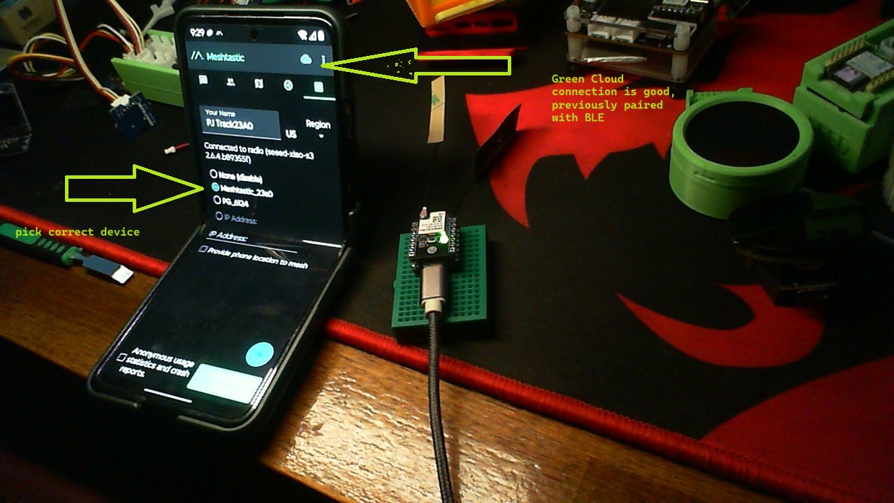
Paired devices earlier are still in app, pick the S3 and wait for Green LED and good connection.
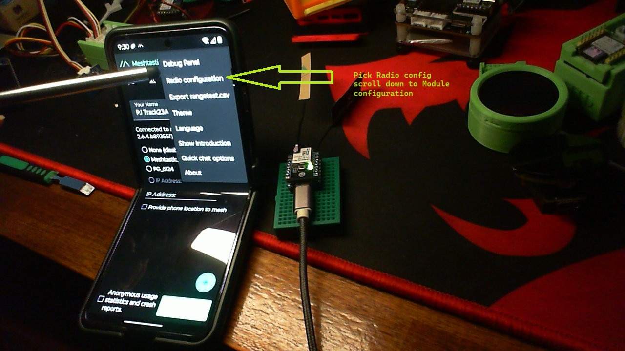
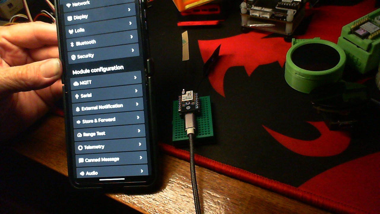
Go to radio configuration, scroll down to Module configuration and pick external Notifications…
I think you can Land it from here… LMK
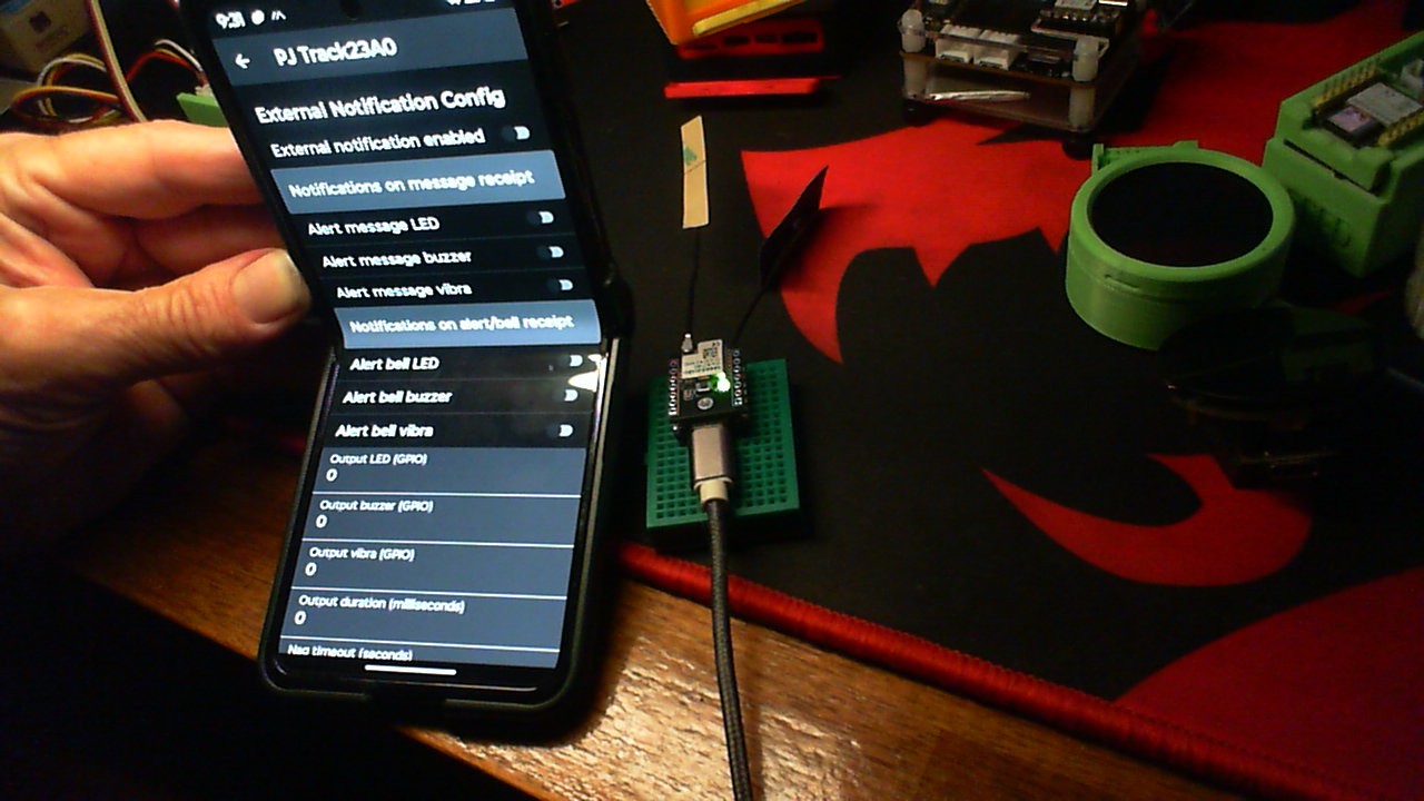
Notifications on Alert/bell RECEIPT
Pick the GPIO you use …
HTH
GL ![]() PJ
PJ ![]()
FYI it works both ways… ![]()
The Pro Move is Sending a message back and clearing the Status or Trigger if you’re Flexing ![]()
![]() “Notification on Message” pick your GPIO once again , ROBERT is your Uncle…
“Notification on Message” pick your GPIO once again , ROBERT is your Uncle… ![]()
@maxmaisy - Not “stupidity” - just “misunderstanding”… Took me a while to wrap my head around what they’re doing with Meshtastic.
There is a video or two that may help with the concepts.
Basically (my understanding) is it is a “standalone” system with various “modules”. You flash the firmware to your “supported” platform and connect via an interface (BLE via mobile app) or
Web via a few options, but Serial most useful with the XIAO’s.
With the Web interface you can create the basic setup for your “private” network and add modules (like Sensor GPIO). I’d use this for the “traps”.
Alternatively add a (non-console) Serial interface to control via an external device. I’d use this for the PC/Laptop/Data Recorder.
Let me know if you want any more information ![]()
And btw , you could probably test with the Button on the Device as well. Don’t over think it or make it more than it needs to be.
Do you have good green LED’s on both units?
Send a message from one to the other first , then Back.
Then look at the radio config , section. They did all the Low level coding for you. Think higher level triggers and messages.
each can cause the other… if that makes sense.
Assign the Button GPIO on one Stack to blink the USER LED assigned on the other S3 (a little hard to see) but you can test it from end to end with what you have there.
HTH
GL ![]() PJ
PJ ![]()
all you need is a USB power bank and your on the way! ![]()
" To use a GPIO pin on a Meshtastic device to send a message, you can leverage the Canned Message Module or the Detection Sensor Module. The Canned Message Module allows pre-defined messages to be sent when a button (connected to a GPIO) is pressed. The Detection Sensor Module allows you to monitor a GPIO for high/low status and send text alerts when a change is detected." from G-man
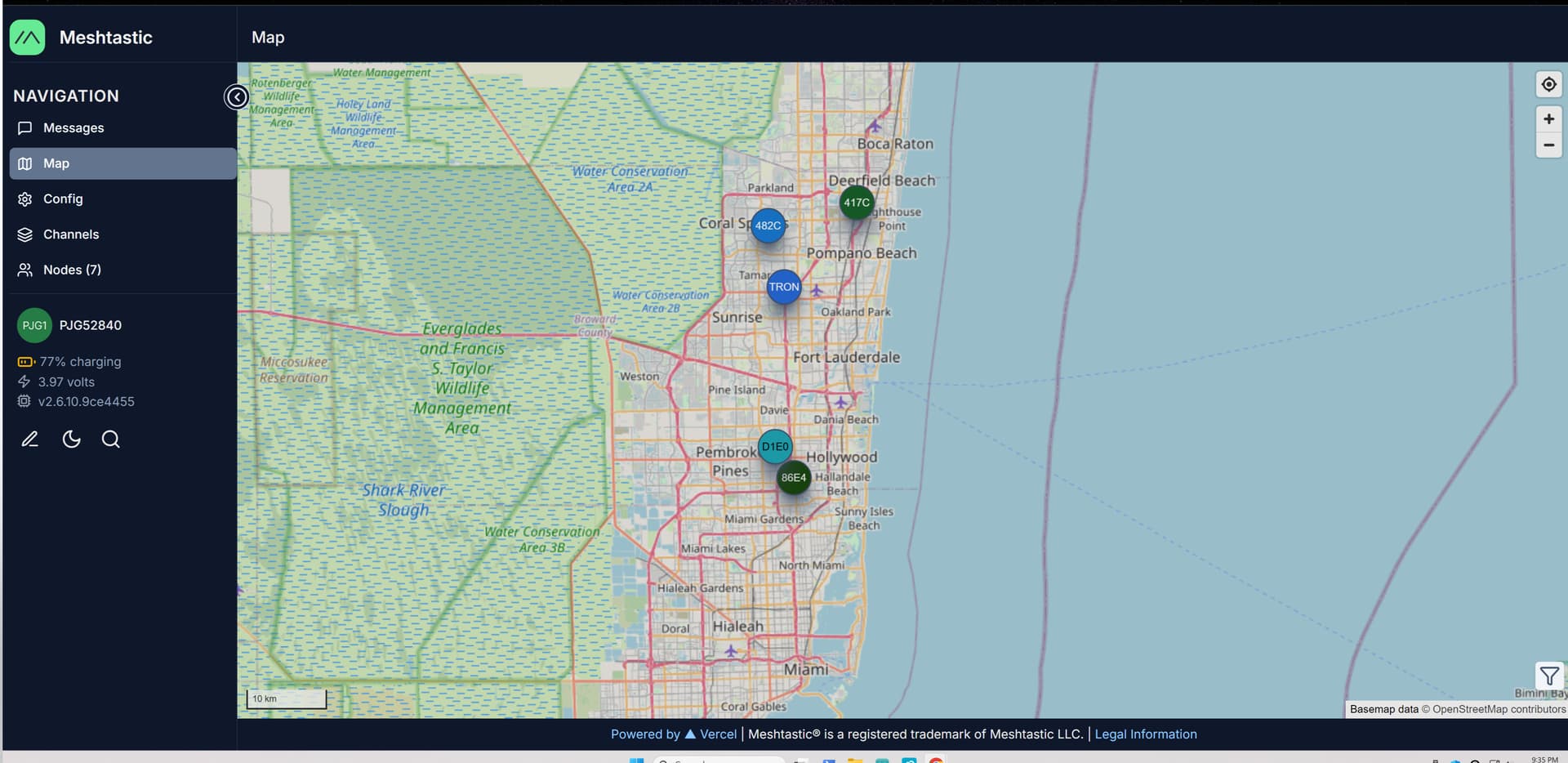
I’m picking up some nodez.,…![]()
![]()
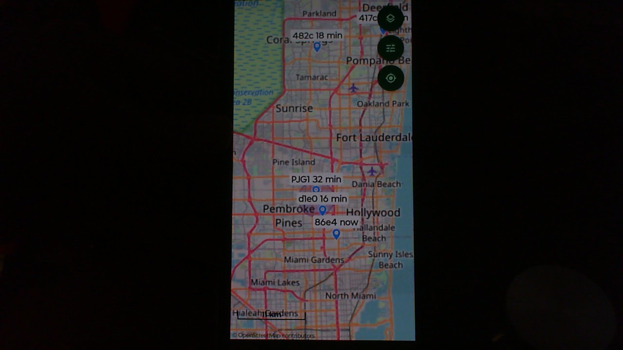
man the web looks better…
Now I understand what I have bought. Thank you for your patience.