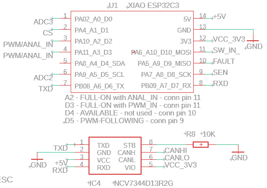
This is the schematic showing CANHI/CANLO and RXD/TXD plus note that this transceiver is running at 5V but interfaces with the ESP32 at 3.3V because VIO is connected to 3V3.
The following code contains all you should need to read TWAI messages:
// check lines with /// for customizing your code
// this is an extract from a much longer program, but should have everything you
	#include <Arduino.h>
	#include "driver/twai.h"					// ESP32-C3 CANbus library
	#define CAN_PWM_ADDR		0x743			// address of PWM message from ECU (unsolicited)
	#define PWM_IN_PIN			D3				// PA11 logical pin 3 physical pin 4 for FULL-ON (also connected to analog mode) from CONNECTOR pin 11
	#define RX_PIN				D7				// Pins used to connect to CAN bus transceiver - RX_PIN - physical pin 8
	#define TX_PIN				D6				// Pins used to connect to CAN bus transceiver - TX_PIN - physical pin 7

	volatile long long	time_start		= 0;	// time PWM ON - pin change
	volatile long long	time_start_prev	= 0;	// previous time PWM ON
	volatile long long	time_stop		= 0;	// time PWM OFF - pin change
	volatile long		period			= 0;	// PWM period length
	volatile long		duty_cycle		= 0;	// PWM Duty Cycle
	volatile long		freq_cntr		= 0;	// PWM Frequency
	volatile int	 	relay_status	= 9;	// PWM input status, ON or OFF, rising or falling, used to switch FOLLOWING-mode relay output
	long				print_switch	= 0;	// debugging print counter
	int			first_time_thru_cntr 	= 0;	// bypass testing for other than PWM until a PWM signal has a chance to be detected
// CAN data variables
	uint32_t 	CAN_lost_timer 			= 0;	// check CAN info signal lost
	long unsigned int rxId;
	unsigned char len					= 0;	// CAN message length
	unsigned char rxBuf[8];						// read buffer
	byte data[8] = {0x00, 0x01, 0x02, 0x03, 0x04, 0x05, 0x06, 0xFE};	// write buffer
	char msgString[128];						// Array to store serial string
	uint32_t 	CAN_lost_delay 			= 1000;	// the number of milliseconds to determine that the CAN signal is lost - 1000 milliseconds
	int			can_begin_cntr 			= 0;	// counter for the number of attempts to start CANbus
//  TWAI definitions
// Read & Send TWAI message Interval
	#define POLLING_RATE_MS 50					/// read only every 1000 msec ****************************** check *******************
	#define TRANSMIT_RATE_MS 500				// transmit frequency - CHANGE TO NEEDED FREQUENCY FOR PRODUCITON *******************
	twai_filter_config_t fConfig;				// fConfig gives access to the configuration struct defined in twai.types.h


// ISR for FULL-ON PWM signal interrupts to calculate duty cycle on PA11 logical pin 3 physical pin 4 from CONNECTOR pin 11
void IRAM_ATTR PWM_FULL_ON()
{	// Check if the interrupt was triggered by a rising edge (HIGH) or falling edge (LOW)
	if (digitalRead(PWM_IN_PIN) == HIGH)
	{	time_start = micros(); 									// save pulse start time
	}
	else
	{	time_stop = micros(); 									// save pulse stop time in microseconds
		period = time_start - time_start_prev;					// calculate wavelength in microseconds
		time_start_prev = time_start;							// save pulse rising start time to previous pulse start time
		duty_cycle = ((time_stop - time_start) * 100 / period);	// calculate duty cycle percent
//		freq_cntr = 500000 / period;							// frequency in Hz
	}
}
void setup()
{	Serial.begin(115200);
	delay(100);
	Serial.println("setup()");
// Initialize configuration structures using macro initializers
	twai_general_config_t g_config = TWAI_GENERAL_CONFIG_DEFAULT((gpio_num_t)TX_PIN, (gpio_num_t)RX_PIN, TWAI_MODE_NORMAL);
	twai_timing_config_t t_config = TWAI_TIMING_CONFIG_500KBITS();	//Look in the api-reference for other speed sets.
//  twai_filter_config_t f_config = TWAI_FILTER_CONFIG_ACCEPT_ALL();
	uint32_t f1_code = (0x743 << 5) << 16;			// move left 5 bits to put ID in 11 high bits and move it to high order 2 register bytes
	uint32_t f1_mask = ((0x0 << 5) | 0x1F) << 16;	// check all 11 bits, but ignore the 5 remaining low order bits
	uint32_t f2_code = (0x200 << 5);				// Accept (compare) 0x200
	uint32_t f2_mask = ((0x1 << 5) | 0x1F);			// 0x1 allows 0x200 and 0x201.  0x1F ignores the first 5 bits
	twai_filter_config_t f_config = {
	fConfig.acceptance_code = f1_code | f2_code,
	fConfig.acceptance_mask = f1_mask | f2_mask,
	fConfig.single_filter = false,
	};

// Install TWAI driver
	if (twai_driver_install(&g_config, &t_config, &f_config) == ESP_OK)
	{	Serial.println("Driver installed");	}
	else
	{	Serial.println("Failed to install driver");
		return;
	}
// Start TWAI driver
	if (twai_start() == ESP_OK)
	{	Serial.println("Driver started");	}
	else
	{	Serial.println("Failed to start driver");
		return;
	}
// Reconfigure alerts to detect frame receive, Bus-Off error and RX queue full states
	uint32_t alerts_to_enable = TWAI_ALERT_RX_DATA | TWAI_ALERT_ERR_PASS | TWAI_ALERT_BUS_ERROR | TWAI_ALERT_RX_QUEUE_FULL;
	if (twai_reconfigure_alerts(alerts_to_enable, NULL) == ESP_OK)
	{	Serial.println("CAN Alerts reconfigured");
	}
	else
	{	Serial.println("Failed to reconfigure alerts");
		return;
	}
// TWAI driver is now successfully installed and started

	//	read alerts here in setup() because it kills [other code] in loop()
	uint32_t alerts_triggered;
	twai_read_alerts(&alerts_triggered, pdMS_TO_TICKS(POLLING_RATE_MS));	/// THIS STATEMENT HANGS PWM FOLLOWING when in loop()
	twai_status_info_t twaistatus;
	twai_get_status_info(&twaistatus);
}
void loop()
{	uint32_t alerts_triggered;
//	twai_read_alerts(&alerts_triggered, pdMS_TO_TICKS(POLLING_RATE_MS));	/// this should work here but interfered with other bits of code
//	twai_status_info_t twaistatus;
//	twai_get_status_info(&twaistatus);
  if (alerts_triggered & TWAI_ALERT_RX_DATA)
	{     // One or more messages received. Handle all.
	      //	Serial.println("Entered message received alert check.");	// for testing omly
	twai_message_t message;
	while (twai_receive(&message, 0) == ESP_OK) {
	  handle_rx_message(message);				}				// GO PROCESS RECEIVED MESSAGE(S) *********
	}

	twai_read_alerts(&alerts_triggered, pdMS_TO_TICKS(POLLING_RATE_MS));
	twai_status_info_t twaistatus;
	twai_get_status_info(&twaistatus);
// Handle alerts
	if (alerts_triggered & TWAI_ALERT_ERR_PASS) {
	Serial.println("Alert: TWAI controller has become error passive.");
	}
	if (alerts_triggered & TWAI_ALERT_BUS_ERROR) {
	Serial.println("Alert: A (Bit, Stuff, CRC, Form, ACK) error has occurred on the bus.");
	Serial.printf("Bus error count: %lu\n", twaistatus.bus_error_count);
	}
// check for TRANSMIT errors
	if (alerts_triggered & TWAI_ALERT_TX_FAILED) {
	Serial.println("Alert: The Transmission failed.");
	Serial.printf("TX buffered: %lu\t", twaistatus.msgs_to_tx);
	Serial.printf("TX error: %lu\t", twaistatus.tx_error_counter);
	Serial.printf("TX failed: %lu\n", twaistatus.tx_failed_count);
	}
	if (alerts_triggered & TWAI_ALERT_TX_SUCCESS) {
	Serial.println("Alert: The Transmission was successful.");
	Serial.printf("TX buffered: %lu\t", twaistatus.msgs_to_tx);
	}
// check for RECEIVE errors
	if (alerts_triggered & TWAI_ALERT_RX_QUEUE_FULL) {
	Serial.println("Alert: The RX queue is full causing a received frame to be lost.");
	Serial.printf("RX buffered: %lu\t", twaistatus.msgs_to_rx);
	Serial.printf("RX missed: %lu\t", twaistatus.rx_missed_count);
	Serial.printf("RX overrun %lu\n", twaistatus.rx_overrun_count);
	}
	//	Serial.println(" Passed error checking and before handle message call");	// for testing only
	// Check if message is received

	if (alerts_triggered & TWAI_ALERT_TX_FAILED) {
	Serial.println("Alert: The Transmission failed.");
	Serial.printf("TX buffered: %lu\t", twaistatus.msgs_to_tx);
	Serial.printf("TX error: %lu\t", twaistatus.tx_error_counter);
	Serial.printf("TX failed: %lu\n", twaistatus.tx_failed_count);
												}
	if (alerts_triggered & TWAI_ALERT_TX_SUCCESS)	{
	Serial.println("Alert: The Transmission was successful.");
	Serial.printf("TX buffered: %lu\t", twaistatus.msgs_to_tx);
													}
// Error recovery
    if (twai_status_info_t status; twai_get_status_info(&status) == ESP_OK) {	// check bus still UP, and recover if not
        if (status.state == TWAI_STATE_BUS_OFF) {
            Serial.println("Bus off error, restarting TWAI...");
            twai_initiate_recovery();
        }
    }		// end of Error recovery
}
// **************************************************************** CANbus message RECEIVE ROUTINE ************************
static void handle_rx_message(twai_message_t& message)
{
//	Serial.println("message received in *handle_rx_message*");	// for testing only
//	Process received message
	if (message.extd)
	{	Serial.println("Message is in Extended Format");	}		// for testing only
	else
	{	Serial.print("Message is in Standard Format");
	}
	Serial.print(" ID=");		// was: Serial.printf(" ID: %lx\nByte:", message.identifier);
	Serial.print(message.identifier, HEX);
	if (!(message.rtr))
	{	for (int i = 0; i < message.data_length_code; i++)
		{	Serial.printf(" %d = %02x,", i, message.data[i]);
		}
//		Serial.println("");			/// end of line println is 4 lines down
	}
// THIS IS THE PLACE TO SELECT AND PROCESS AN INCOMING CANbus MESSAGE OF INTEREST (IF CAN USED INSTEAD OF PWM or ANALOG FROM ECU) ******************
	if (message.identifier == CAN_PWM_ADDR) 							// PWM FROM ECU VIA CAN BUS
	{	Serial.print(" rxId - in loop = ");	Serial.println(message.identifier, HEX);
///		duty_cycle = message.data[1];					// pick a location for the duty cycle in the CANbus message for relay operation
///		duty_cycle = map(duty_cycle, 0, 255, 0, 100);	// duty cycle from ECU NEEDS TO BE CUSTOMIZED (either 0 to 100 or 0 - 255 or ???)
		duty_cycle = message.data[1] * 2;				/// this was for my test setup only
		rxId = 0;									// reset rxId so this routine won't execute until another CAN 743 msg is received
	}

}	// end of rxId = CAN_PWM_ADDR (743)
//*************************************** end of CANbus message RECEIVE ROUTINE ****************************