I’ve got 20 of the new XIAO ESP32S3 Plus boards, and I’m trying to learn about the ADC_BAT label connected to GPIO10 on the board schematic. I was hopeful that this would allow battery voltage measurements, but I’m not seeing any connection to the battery circuit, or a voltage divider.
Am I missing anything here? I’m curious about the nature of this label in the schematic.
On the XIAO ESP32S3 Plus, the label ADC_BAT typically refers to the battery voltage sense line, and on this board it’s connected to GPIO10, which is an analog-capable pin.
What is ADC_BAT?
ADC_BAT is used to measure the voltage level of the battery.
It connects to an analog input (GPIO10) that lets the ESP32S3 read the battery voltage via its internal ADC (Analog to Digital Converter).
Often, there’s a resistor voltage divider between the battery and this pin to ensure the voltage stays within safe ADC levels (typically under 3.3V).
Why is this useful?
It allows your code to monitor battery level.
You can shut down peripherals or enter deep sleep when the battery gets low.
You can display battery % on-screen or transmit it wirelessly.
Example: Read battery voltage from ADC_BAT
Here’s a simple Arduino sketch to read the voltage on GPIO10 (ADC_BAT):
Thanks PJ! This is what I had expected (and hoped for), but I don’t see any evidence that this pin is actually connected to the battery circuit or a voltage divider for measurement. Maybe something is hiding that I don’t see, but it appears to be a false advertisement in the schematic—maybe something planned initially but was never implemented?
I’m curious if there’s a way to consult the engineers or devs that designed the Plus model of the XAIO ESP32S3. Do those folks frequent these discussions?
Sure thing, We all want to know. So I have a couple in route so I’ll be able to put hands on and test. I couldn’t find anything even in the technical reference guide. Unlike them to to stretch that far i’m thinking…
It seems more likely that the ADC_BAT label is a mistake in the schematic (or the label is correct but further details are missing in the schematic, which seems less likely).
Well, if you have been around Seeed Studio devices, you know.
It’s a 50/50 proposition. Odd it’s in a few Places so , the pins spreadsheet for example? Let’s see if more info comes.
Fair enough. Yeah, I did notice the label in the pinout spreadsheet. In some instances, I know there is a requirement to write a certain pin high to enable an ADC, which may be the case here. There’s also this in the wiki for the non-Plus XIAO ESP32S3, which suggests this may have been a planned improvement for the Plus board:
Quick update: since the voltage divider circuit is not present on the board, I tested a quick battery measurement using GPIO10 and my own voltage divider with 2x220K resistors, and it works great that way.
Just ran across this myself! Glad I checked the schematic and forum rather than trusting the symbol. Quick question, why do we need a voltage divider? Can I not just wire the battery + into a GPIO with ADC and read the voltage? Is it just because the voltage can go over 3.3?
And if a voltage divider is required, what resistor values should be used? I assume we’d want the resistance to be high to minimize power draw, but is there a limit?
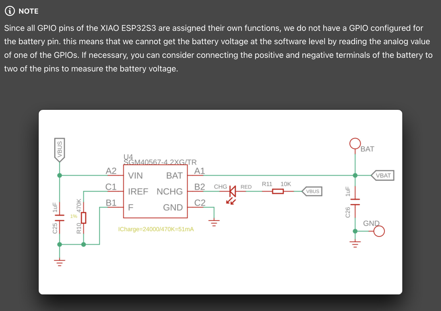
The charge controller charges the battery to 4.2V, which exceeds the allowable voltage of the port. A voltage divider is needed to keep the voltage below the allowable 3.3V.
The maximum resistor that can be used for the voltage divider would be 1000k.
With the ADC, we need to limit voltage to under 3.3V, or slightly less when you factor in ADC attenuation. In my case, I used a voltage divider with an output ratio of 1/2 by using two equal-value resistors. This allows for a 1S lipo battery to be measured at full capacity (4.2V reads at 2.1V).
That’s worked well for me, but now I’m noticing some variability at lower voltage levels. Your post is a timely coincidence as I’m right in the middle of gathering more data. My limited understanding is that higher resistance reduces current draw, yes, but can also add noise to the ADC readings. I somewhat hastily chose a pair of 200 kohm resistors to limit current draw, but now I’m second guessing that. Before I try lower-value resistors, I’m going to add a 100 nF capacitor between the ADC and ground to see if that makes some difference in noise and fluctuations at lower input voltages.
Your #2 reason is the reasoning I’ve come to understand, so hopefully the capacitor helps. By chance, have you experimented with lower resistor values to see if that makes any difference without needing the capacitor? It would help with my current PCB design to avoid needing the capacitor if reasonably possible. Thanks!!
I have tried using 220k, but there was a difference of 10-20mV or more from the multimeter readings.
The ESP32 datasheet recommends connecting a capacitor to the AD conversion input, and I believe the conversion accuracy values were written on the assumption that a capacitor was present.
Very helpful, thank you! I’ll take a look at that.
Would you mind sharing the resistor and capacitor values you settled on?
I’ve collected a bunch of samples from a voltage sensor and ADC readings, and then ran a linear regression to create a function to convert from ADC value to mV, but if I can get the ADC to report an accurate value, that would certainly be better.
Since my purpose is to monitor (not measure) battery voltage, I do not need AD conversion accuracy.
Considering current consumption, I divide the voltage by 1/2 with selected 1000k+1000k and do not use a capacitor. I use the value averaged about 100 times.
The accuracy of the ESP32’s AD converter is not very good. Especially when BLE or WiFi is operated, there may be a lot of noise on the input.
Okay, that makes sense. Thank you for sharing and helping!
In case anyone finds this later, yes, the 100 nF capacitor between the ADC pin and ground did instantly eliminate my noise issues. Oddly, noise was only present near 3.6V. Above and below (3.4V or 3.8V), it was fine. I expected more noise as voltage decreased, but that wasn’t the case. With the capacitor, very little noise across the full range. I’m still using 2x 200 kohm resistors.
Hi! Yes, this configuration has been working very well for me. The only reason I’m aware of to lower the resistor value would be to reduce noise effects. In my case, the 100 nF capacitor removed all significant noise while allowing me to keep the 200 kohm resistors.
Of course, if your input voltage exceeds much more than about 4.2V then you’ll need to adjust the resistor values in the voltage divider accordingly.