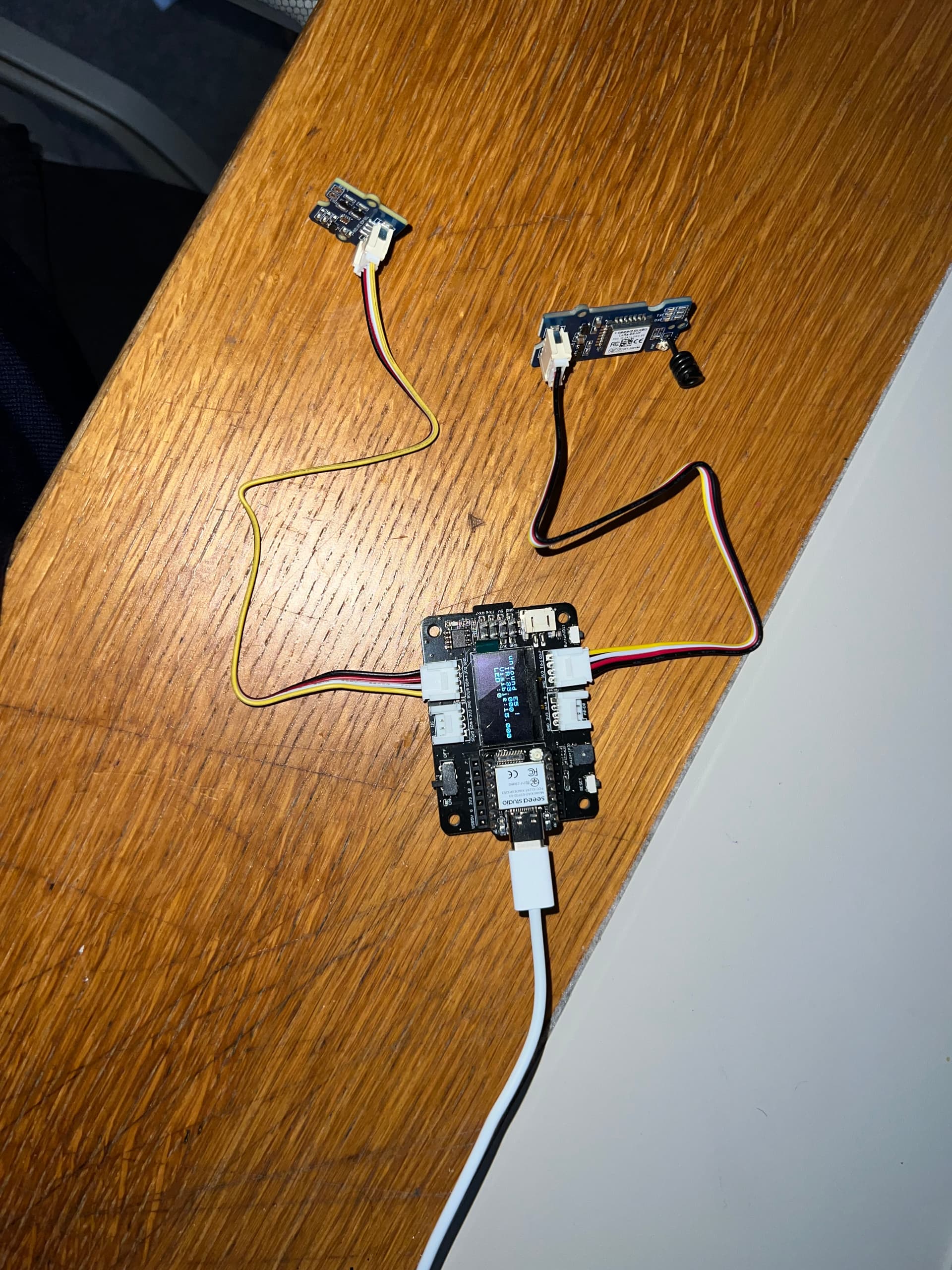
Hi, I am also new to the LoRa and LoRaWan World. I have an XIAO ESP32S3 and the expansion board as well as the Grove Wio E5 and I am trying to use it with TTN however when I use the code provided on Grove - Wio-E5 TTN Demo | Seeed Studio Wiki it does not seem to detect the wio module. I have tweaked the code to send data from the Grove Sunlight Sensor but the core functionality does not work as it does not seem to find the wio module. this is my code: When i run this I get the output printing out the IR and Visible values however initially i get: No E5 module found. I am really confused why and cant seem to get anything working. I have run some code from GitHub - andresoliva/LoRa-E5: Advanced application of SeedStudio module Grove-Wio-E5 based on chip STM32WLE5JC from STM connected to an Arduino Nano 33 BLE Sense board. Works with any Arduino that supports UART. This confused me more since I got a response which was a devEui however the setup on the TTN did not seem to get any data and it seems like that code breaks quite a lot of fair play policies. Any help will be appreciated. I have attached an image of my setup as well as pasted the code below.
#include <Arduino.h>            // Include Arduino core library
#include <U8x8lib.h>            // Include U8x8 library for OLED display
#include <Wire.h>               // Include Wire library for I2C communication
#include "Si115X.h"             // Include Si115X sensor library

Si115X si1151;                  // Create an instance of Si115X sensor

U8X8_SSD1306_128X64_NONAME_HW_I2C u8x8(/*reset=*/U8X8_PIN_NONE); // Create an instance of OLED display

static char recv_buf[512];      // Buffer to store received data
static bool is_exist = false;   // Flag to check if E5 module exists
static bool is_join = false;    // Flag to check if LoRaWAN network is joined
static int led = 0;             // LED state

// Function to send AT command and check response
static int at_send_check_response(char *p_ack, int timeout_ms, char *p_cmd, ...)
{
    int ch;
    int num = 0;
    int index = 0;
    int startMillis = 0;
    va_list args;
    memset(recv_buf, 0, sizeof(recv_buf)); // Clear receive buffer
    va_start(args, p_cmd);
    Serial1.printf(p_cmd, args);   // Print formatted command to Serial1
    Serial.printf(p_cmd, args);     // Print formatted command to Serial
    va_end(args);
    delay(200);
    startMillis = millis(); // Get current time

    if (p_ack == NULL)
    {
        return 0;
    }

    do
    {
        while (Serial1.available() > 0)
        {
            ch = Serial1.read();
            recv_buf[index++] = ch; // Store received character
            Serial.print((char)ch); // Print received character
            delay(2);
        }

        if (strstr(recv_buf, p_ack) != NULL) // Check if expected response received
        {
            return 1;
        }

    } while (millis() - startMillis < timeout_ms); // Continue until timeout
    return 0;
}

// Function to parse received message
static void recv_prase(char *p_msg)
{
    if (p_msg == NULL)
    {
        return;
    }
    char *p_start = NULL;
    int data = 0;
    int rssi = 0;
    int snr = 0;

    // Parse received data
    p_start = strstr(p_msg, "RX");
    if (p_start && (1 == sscanf(p_start, "RX: \"%d\"\r\n", &data)))
    {
        // Print received data to serial monitor
        Serial.println(data);
        // Display LED status on OLED
        u8x8.setCursor(2, 4);
        u8x8.print("led :");
        led = !!data;
        u8x8.print(led);
        // Toggle LED
        if (led)
        {
            digitalWrite(LED_BUILTIN, LOW);
        }
        else
        {
            digitalWrite(LED_BUILTIN, HIGH);
        }
    }

    p_start = strstr(p_msg, "RSSI");
    if (p_start && (1 == sscanf(p_start, "RSSI %d,", &rssi)))
    {
        // Display RSSI value on OLED
        u8x8.setCursor(0, 6);
        u8x8.print("                ");
        u8x8.setCursor(2, 6);
        u8x8.print("rssi:");
        u8x8.print(rssi);
    }
    p_start = strstr(p_msg, "SNR");
    if (p_start && (1 == sscanf(p_start, "SNR %d", &snr)))
    {
        // Display SNR value on OLED
        u8x8.setCursor(0, 7);
        u8x8.print("                ");
        u8x8.setCursor(2, 7);
        u8x8.print("snr :");
        u8x8.print(snr);
    }
}

// Arduino setup function
void setup(void)
{
    u8x8.begin();                               // Initialize OLED display
    u8x8.setFlipMode(1);
    u8x8.setFont(u8x8_font_chroma48medium8_r);

    Serial.begin(115200);                       // Initialize serial communication
    pinMode(LED_BUILTIN, OUTPUT);               // Set LED pin as output
    digitalWrite(LED_BUILTIN, HIGH);            // Turn off LED

    Serial1.begin(9600);                        // Initialize serial communication with E5 module
    Serial.print("E5 LORAWAN TEST\r\n");
    u8x8.setCursor(0, 0);

    Wire.begin();                               // Initialize I2C communication
    if (!si1151.Begin()) {
        Serial.println("Si1151 is not ready!");
        while (1) {
            delay(1000);
            Serial.print(".");
        };
    } else {
        Serial.println("Si1151 is ready!");
    }

    // Check if E5 module exists and configure LoRaWAN parameters
    if (at_send_check_response("+AT: OK", 100, "AT\r\n"))
    {
        is_exist = true;
        at_send_check_response("+ID: AppEui", 1000, "AT+ID\r\n");
        at_send_check_response("+MODE: LWOTAA", 1000, "AT+MODE=LWOTAA\r\n");
        at_send_check_response("+DR: EU868", 1000, "AT+DR=EU868\r\n");
        at_send_check_response("+CH: NUM", 1000, "AT+CH=NUM,0-2\r\n");
        at_send_check_response("+KEY: APPKEY", 1000, "AT+KEY=APPKEY,\"2B7E151628AED2A6ABF7158809CF4F3C\"\r\n");
        at_send_check_response("+CLASS: C", 1000, "AT+CLASS=A\r\n");
        at_send_check_response("+PORT: 8", 1000, "AT+PORT=8\r\n");
        delay(200);
        u8x8.setCursor(5, 0);
        u8x8.print("LoRaWAN");
        is_join = true;
    }
    else
    {
        is_exist = false;
        Serial.print("No E5 module found.\r\n");
        u8x8.setCursor(0, 1);
        u8x8.print("unfound E5 !");
    }

    u8x8.setCursor(0, 2);
    u8x8.setCursor(2, 2);
    u8x8.print("IR:");

    u8x8.setCursor(2, 3);
    u8x8.print("Visible:");

    u8x8.setCursor(2, 4);
    u8x8.print("LED :");
    u8x8.print(led);
}

// Arduino loop function
void loop(void)
{
    float irValue = si1151.ReadIR();       // Read IR value from sensor
    float visibleValue = si1151.ReadVisible(); // Read visible light value from sensor

    Serial.println("IR: " + String(irValue) + " Visible: " + String(visibleValue)); // Print sensor values to serial monitor

    u8x8.setCursor(0, 2);
    u8x8.print("      ");
    u8x8.setCursor(2, 2);
    u8x8.print("IR:");
    u8x8.print(irValue);
    u8x8.setCursor(2, 3);
    u8x8.print("Visible:");
    u8x8.print(visibleValue);

    // If E5 module exists, perform LoRaWAN operations
    if (is_exist)
    {
        int ret = 0;
        if (is_join)
        {
            // Attempt to join LoRaWAN network
            ret = at_send_check_response("+JOIN: Network joined", 12000, "AT+JOIN\r\n");
            if (ret)
            {
                is_join = false;
            }
            else
            {
                at_send_check_response("+ID: AppEui", 1000, "AT+ID\r\n");
                Serial.print("JOIN failed!\r\n\r\n");
                delay(5000);
            }
        }
        else
        {
            // Send sensor data over LoRaWAN
            char cmd[128];
            sprintf(cmd, "AT+CMSGHEX=\"%04X%04X\"\r\n", (int)irValue, (int)visibleValue);
            ret = at_send_check_response("Done", 5000, cmd);
            if (ret)
            {
                recv_prase(recv_buf); // Parse received response
            }
            else
            {
                Serial.print("Send failed!\r\n\r\n");
            }
            delay(5000);
        }
    }
    else
    {
        delay(1000);
    }
}
