Dear all,
new (part) project,new problems… I wish ppl in this line of field would start making stuff which just works or follows documentation…
Case in point, a load cell 20kg with a HX 711 amplifier:
https://nl.aliexpress.com/item/1005007205148171.html?spm=a2g0o.order_list.order_list_main.4.32f279d2gEcWru&gatewayAdapt=glo2nld
Thing simply does not work. The load cell has 4 wires, which are connected to the board. The board then has GND DT SCK and VPP.
Connected GND to ground on the ESP, VPP to the +5V, DT to pin 2, SCK to pin 3.
Installed the HX711 library (the bogdan one), run example… does not work. HX711 not found.
The board should pull the data pin down when it’s ready. However, measuring it shows near 5v.
Readig… the HX711 needs pulldowns. So added to the code:
pinMode(LOADCELL_DOUT_PIN, INPUT_PULLDOWN);
pinMode(LOADCELL_SCK_PIN, INPUT_PULLDOWN);
This solves the hx711 not found issue. However I still do not get any measurement from it.
Then I found this:
I have this board:
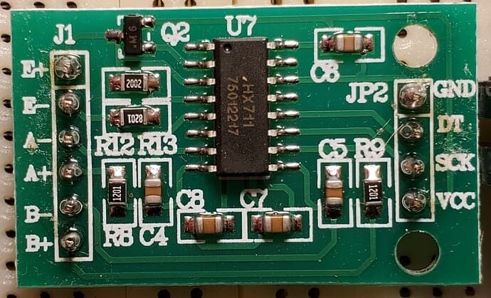
(foto from that thread, not my board)
In that thread it claims this board has an open e-, which is correct. They claim this should be connected to GND. SO i did that. No change.
I’m measuring the correct voltages from the load cell itself (as in beforementioned topic).
Am I using the wrong pins on the arduino?
Anyone have this combo working? There are several pages with ppl who have it work, without issues. Is my HX711 broken?