Hi there ,
Ok so It works no issue’s Led lights every time through the loop the Built-in on io21 and and external connected thru a 220 ohm resistor to 3.3v connected to the bottom pin io42 the Serial output is the touch pin value (typical 24-29) touched over 1000.
Here is the code I used.
const int touch_pin = A5;
int LED_pin = 21;
int MTMS_pin = 42;
void setup(void) {
  Serial.begin(9600);
  delay (1000);
  // declaring LED pin as output
  pinMode(LED_pin, OUTPUT);
  pinMode(MTMS_pin, OUTPUT);
}

void loop(void) {
   // turn on:
    digitalWrite(LED_pin, HIGH);
    digitalWrite(MTMS_pin, HIGH);
    delay(500);
  Serial.print("Touch value: ");
  Serial.println(analogRead(touch_pin));
  delay(1000);
// turn off:
  digitalWrite(LED_pin, LOW);
  digitalWrite(MTMS_pin,LOW);
  delay(500);
}
Here the output;
mode:DIO, clock div:1
load:0x3fce3808,len:0x44c
load:0x403c9700,len:0xbe4
load:0x403cc700,len:0x2a38
entry 0x403c98d4
Touch value: 41
Touch value: 33
Touch value: 18
Touch value: 27
Touch value: 26
Touch value: 1083
Touch value: 1107
Touch value: 1159
Touch value: 25
Touch value: 31
Here is the connected DUT
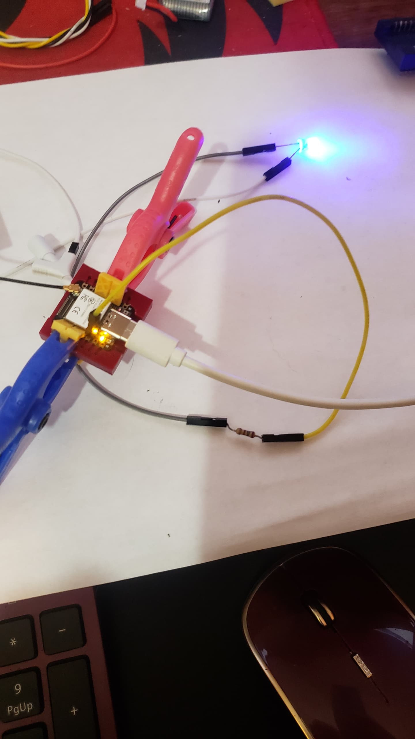
Got a little HOT when setting the pins, Don’t be in a hurry.

These is the pogo pins.

Bottom Filmed on a Potato So…

Here’s the pins. I connected the White jumper to the MTMS (GPIO42)

From the pins file…
MTDI	47	I/O/T	VDD3P3_CPU	MTDI	GPIO41	CLK_OUT1  D12	PDM_DATA GPIO41	MTDI
MTMS	48	I/O/T	VDD3P3_CPU	MTMS	GPIO42		      D11	PDM_CLK	 GPIO42	MTMS
HTH
So you can use the pins on the bottom for IO, AFAIK.
GL ![]() PJ
PJ
Here is the ZIP containing the Socket, you can print your own, add the pins and make the legs or look at the other socket thread and see how it’s done. ENJOY.
XiAO_Socket_ESP32S3-Body.rar (59.7 KB)