Hi, I am new here I want to know anyone tested xiao esp32-s3 jtag pins as gpio
How to use Xiao Esp32-s3 JTAG pins as GPIO pins?
I agree,
All strapping pins have latches. At system reset, the latches sample the bit values of their
 respective strapping pins and store them until the chip is powered down or shut down.
The states of latches cannot be changed in any other way. It makes the strapping pin
values available during the entire chip operation,
and the pins **are freed up to be used as regular IO pins** after reset.
from the wiki
HTH
GL ![]() PJ
PJ
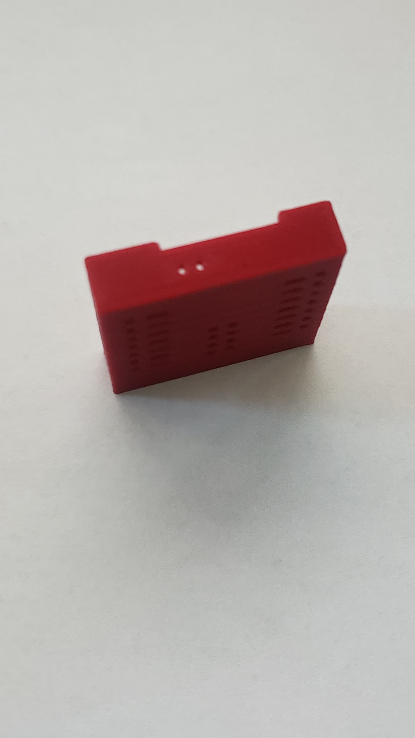
ps. I’m currently working on 3D printing a socket that has the connections from the bottom available. Stay Tunned.
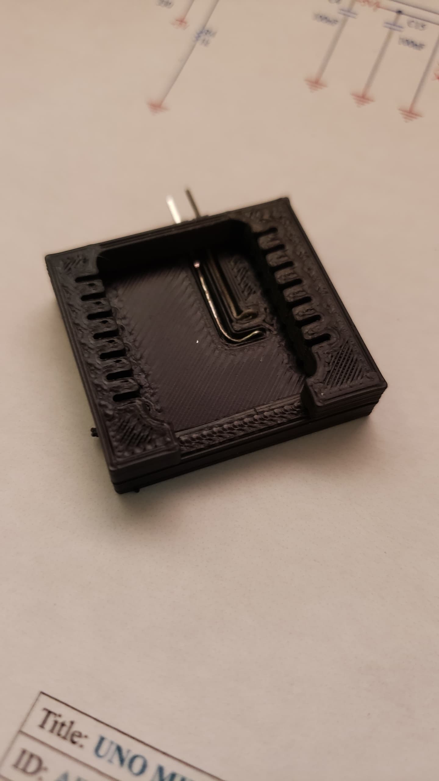
Like this but with pogo pins…

Hi there ,
Ok so It works no issue’s Led lights every time through the loop the Built-in on io21 and and external connected thru a 220 ohm resistor to 3.3v connected to the bottom pin io42 the Serial output is the touch pin value (typical 24-29) touched over 1000.
Here is the code I used.
const int touch_pin = A5;
int LED_pin = 21;
int MTMS_pin = 42;
void setup(void) {
  Serial.begin(9600);
  delay (1000);
  // declaring LED pin as output
  pinMode(LED_pin, OUTPUT);
  pinMode(MTMS_pin, OUTPUT);
}

void loop(void) {
   // turn on:
    digitalWrite(LED_pin, HIGH);
    digitalWrite(MTMS_pin, HIGH);
    delay(500);
  Serial.print("Touch value: ");
  Serial.println(analogRead(touch_pin));
  delay(1000);
// turn off:
  digitalWrite(LED_pin, LOW);
  digitalWrite(MTMS_pin,LOW);
  delay(500);
}
Here the output;
mode:DIO, clock div:1
load:0x3fce3808,len:0x44c
load:0x403c9700,len:0xbe4
load:0x403cc700,len:0x2a38
entry 0x403c98d4
Touch value: 41
Touch value: 33
Touch value: 18
Touch value: 27
Touch value: 26
Touch value: 1083
Touch value: 1107
Touch value: 1159
Touch value: 25
Touch value: 31
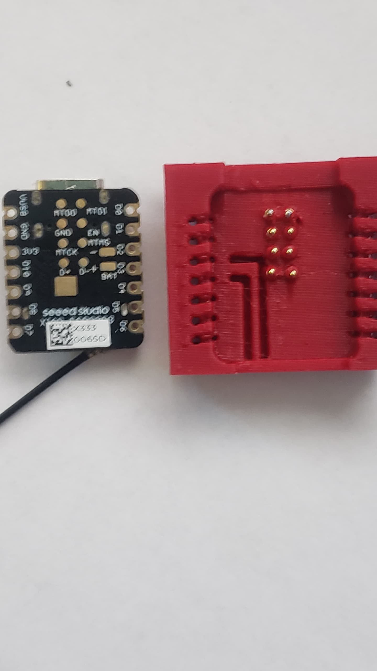
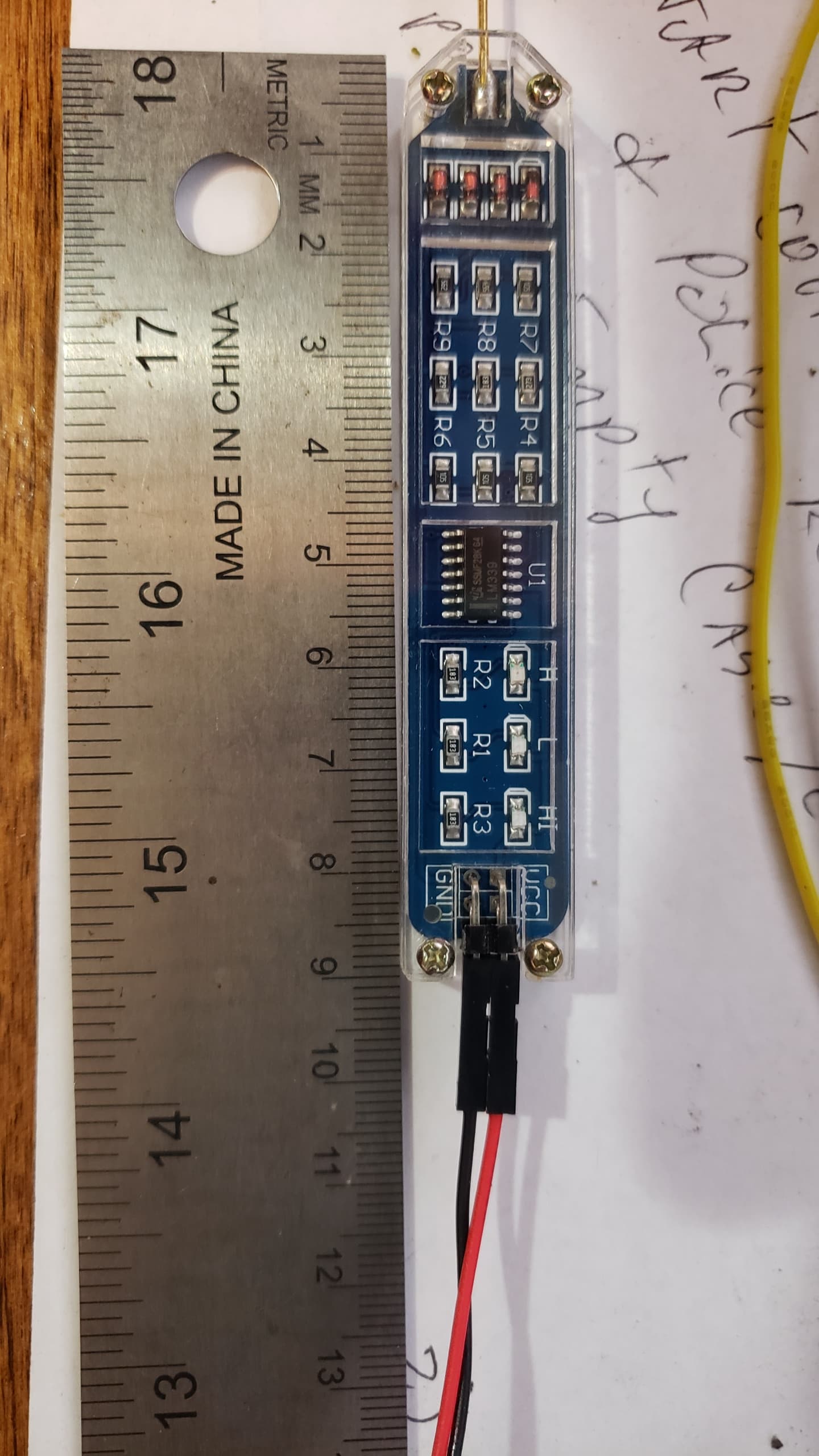
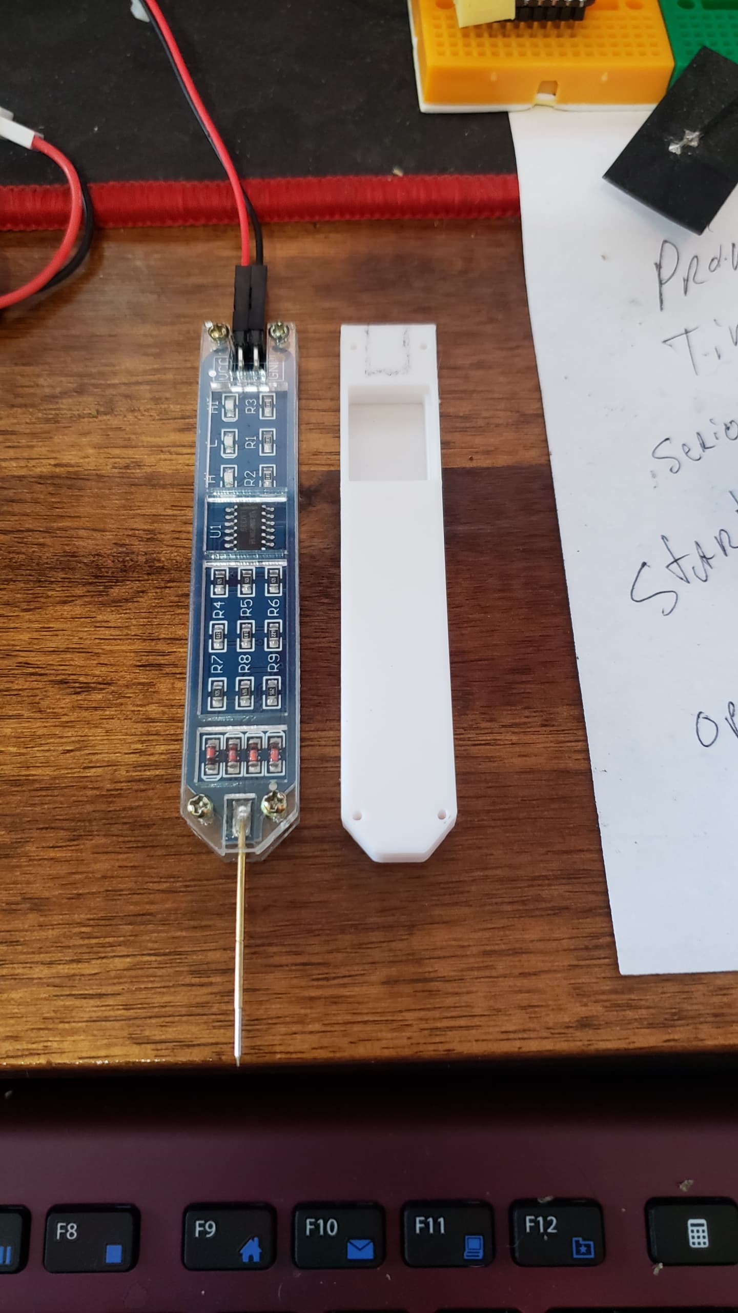
Here is the connected DUT
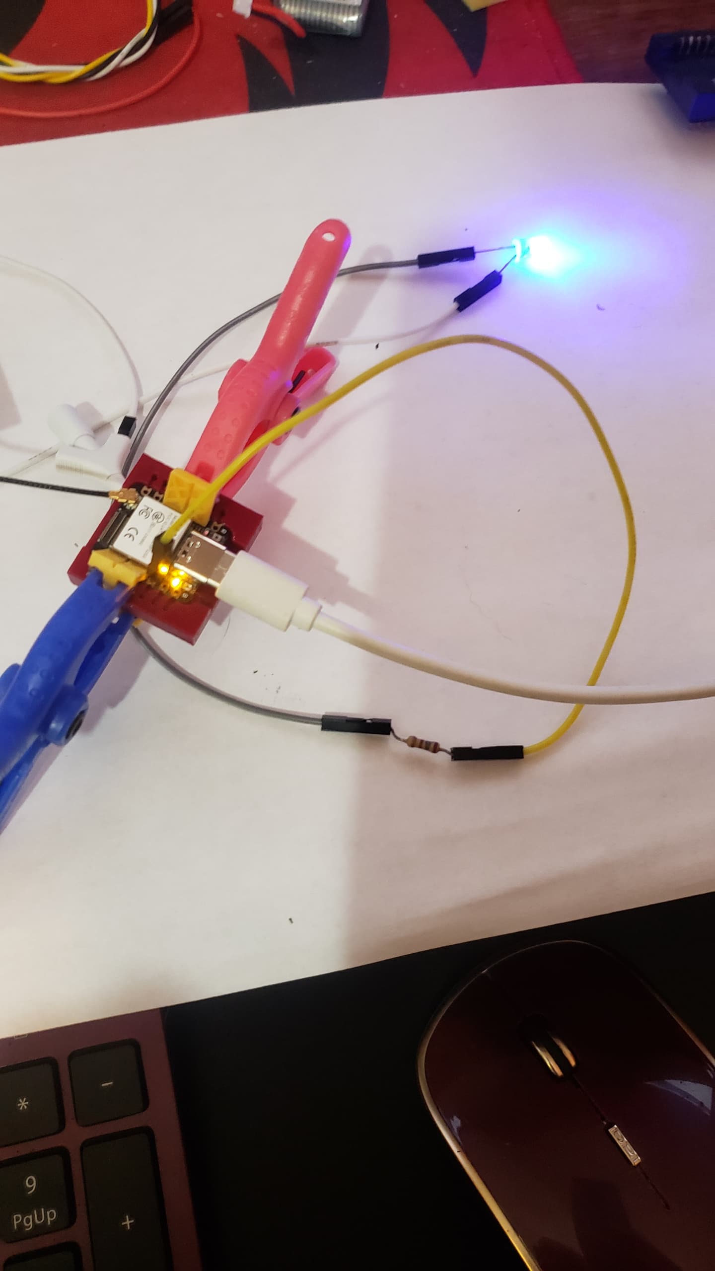
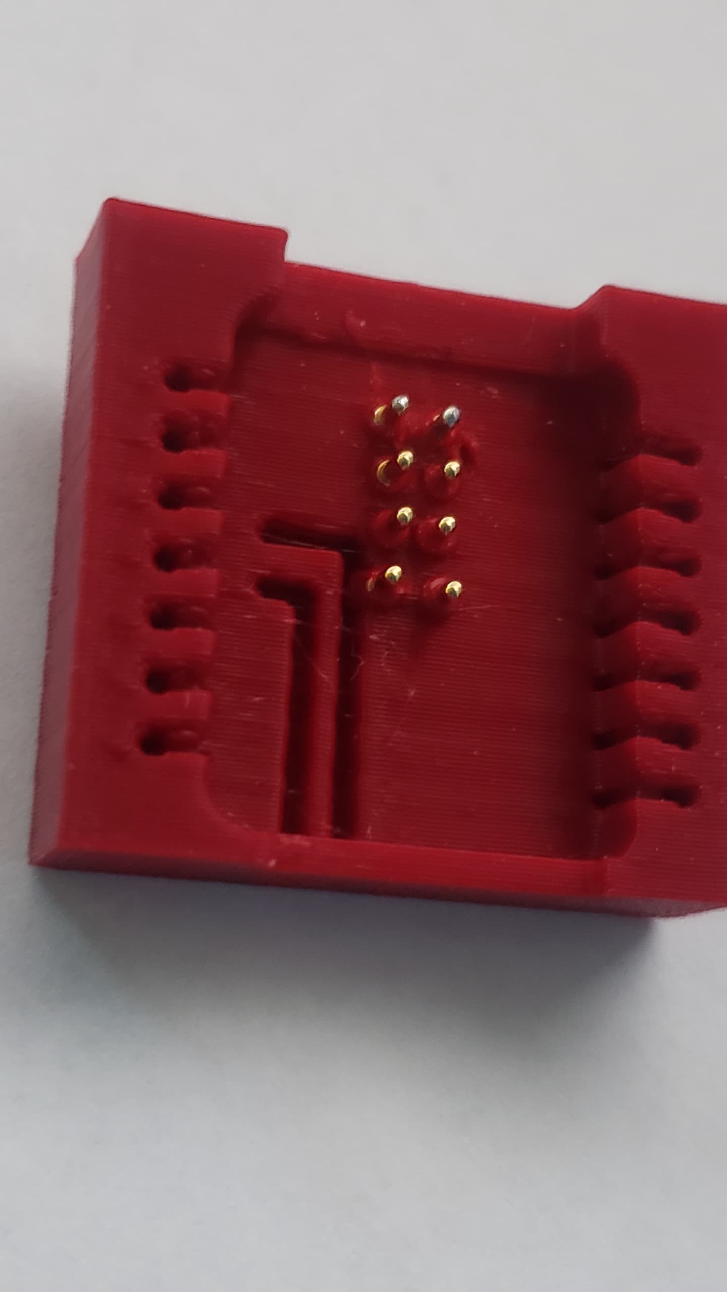
Got a little HOT when setting the pins, Don’t be in a hurry.

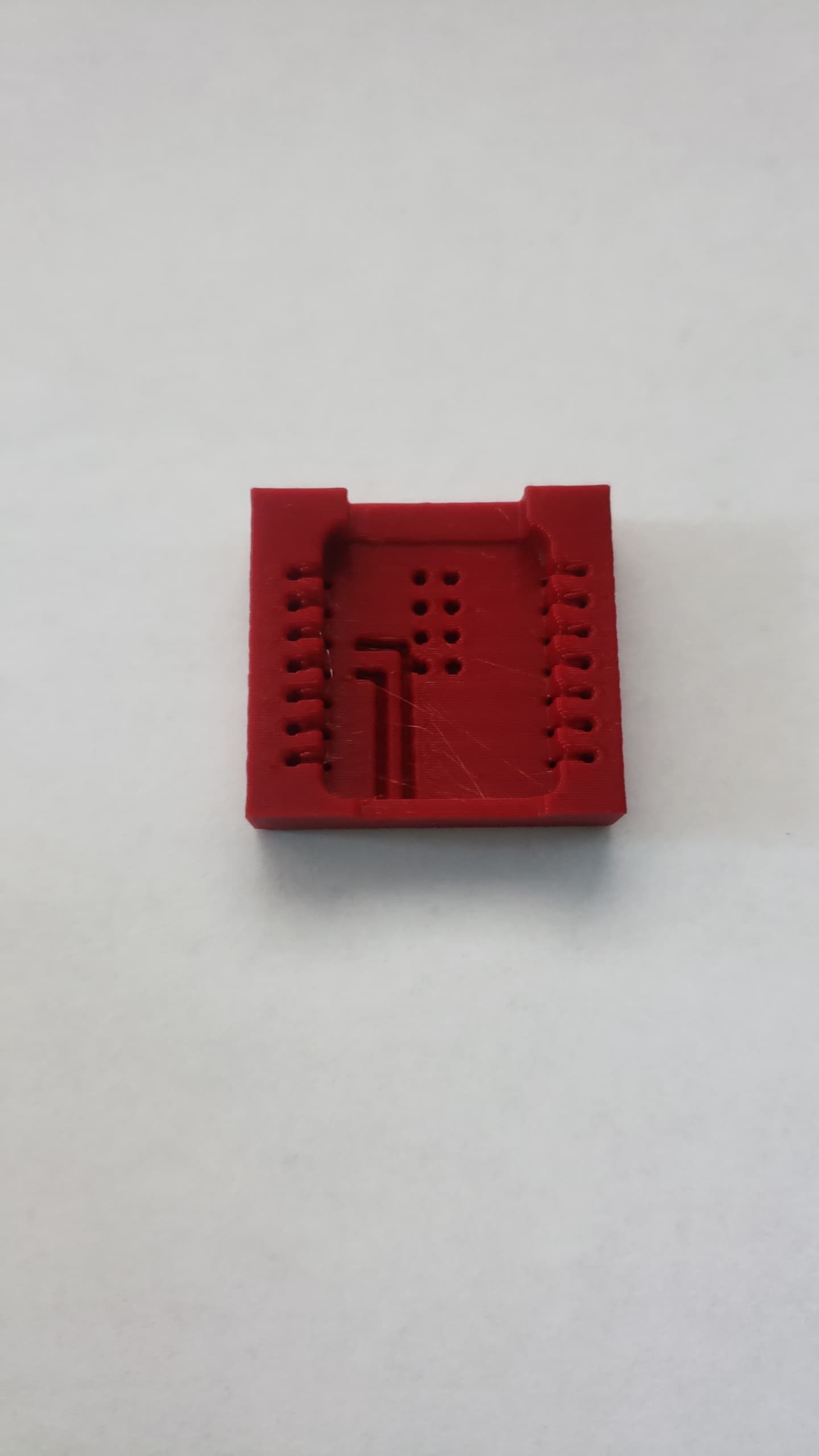
These is the pogo pins.

Bottom Filmed on a Potato So…

Here’s the pins. I connected the White jumper to the MTMS (GPIO42)

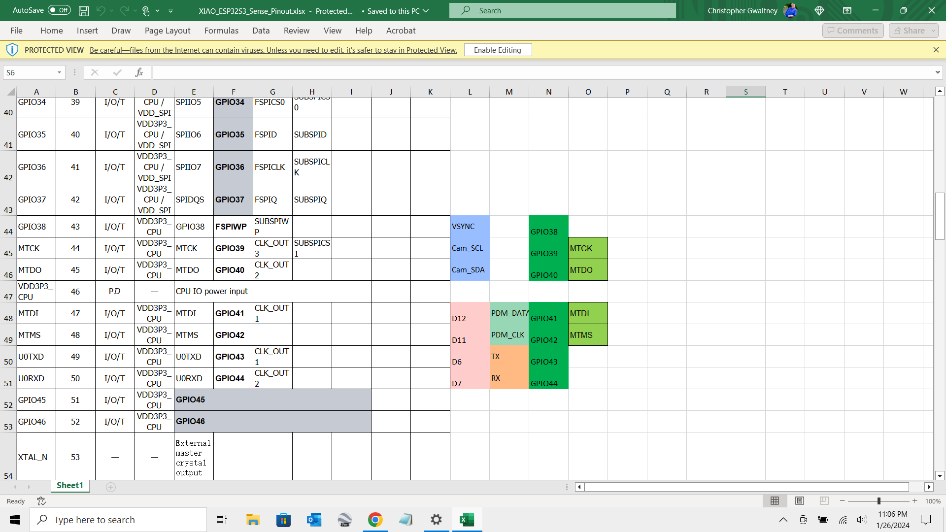
From the pins file…
MTDI	47	I/O/T	VDD3P3_CPU	MTDI	GPIO41	CLK_OUT1  D12	PDM_DATA GPIO41	MTDI
MTMS	48	I/O/T	VDD3P3_CPU	MTMS	GPIO42		      D11	PDM_CLK	 GPIO42	MTMS
HTH
So you can use the pins on the bottom for IO, AFAIK.
GL ![]() PJ
PJ
Here is the ZIP containing the Socket, you can print your own, add the pins and make the legs or look at the other socket thread and see how it’s done. ENJOY.
XiAO_Socket_ESP32S3-Body.rar (59.7 KB)
Thank you
Designer have added header pins bottom in design so it will com with pins.
So we can use them as gpio with out changing efuses and there is no issue using them as gpio
Thanks for testing.
")
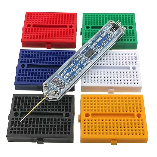

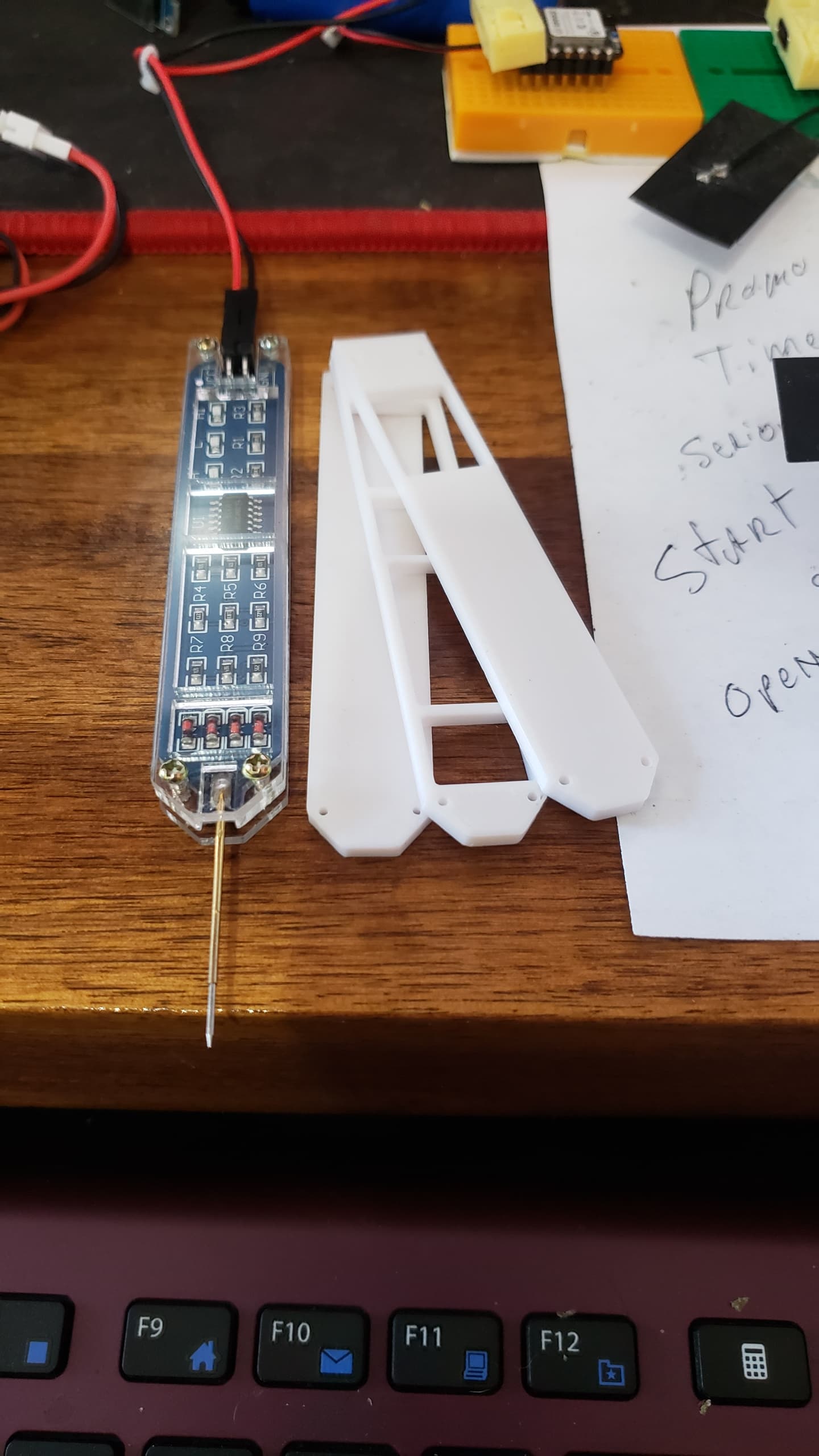
Where did you get the plastic cover for the logic probe ?
Hi there,
Came with it, three pieces you put them on, Really great , no need to reach for the voltmeter or scope for just a quick logic test and output verification.
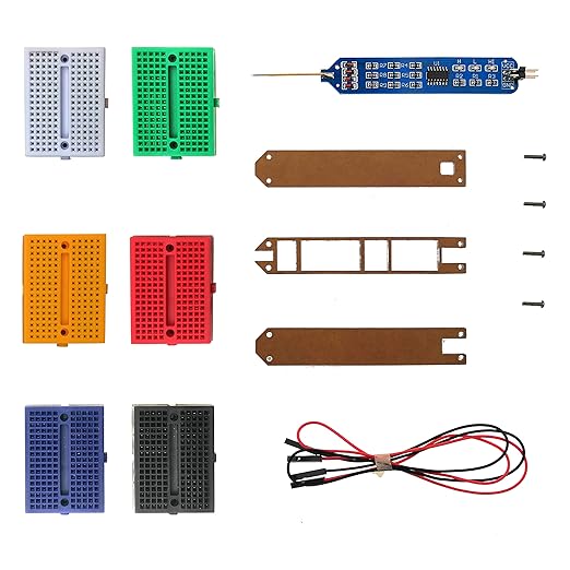
https://www.amazon.com/dp/B08J7JSM3T?ref=ppx_yo2ov_dt_b_product_details&th=1
HTH
GL ![]() PJ
PJ
![]()
Thanks, I have a couple of the logic probes, well useful, but they did not come with a cover.
Hi there,
Yea I had an OLD 5v TTL only ,saw this cheepy with the blocks too. My Mouse has AI in it, ![]() Ended up in the cart?
Ended up in the cart? ![]()
You could always 3D print one easy, got a picture?
GL ![]() PJ
PJ ![]()
Its the same one in your picture, just no case.
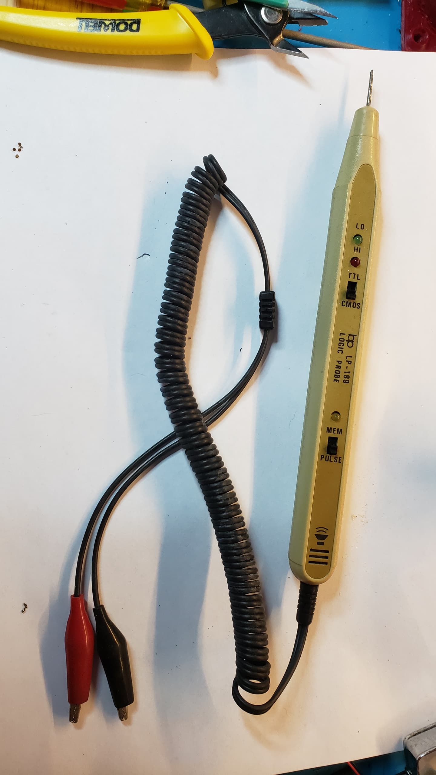
Back in the 80s when I was fixing the early microcontroller boards and BBC Micros by far one of the best tools was one of these;
I still have the one I used bck then somewhere, but its 5V logic so not a lot of use on ‘modern’ stuff.
LoL,same church different pew.![]()
![]()
I’ll dig out my original snap a picture, ah’ I’ll take a crack at modeling a copy and post it up.
GL ![]() PJ
PJ
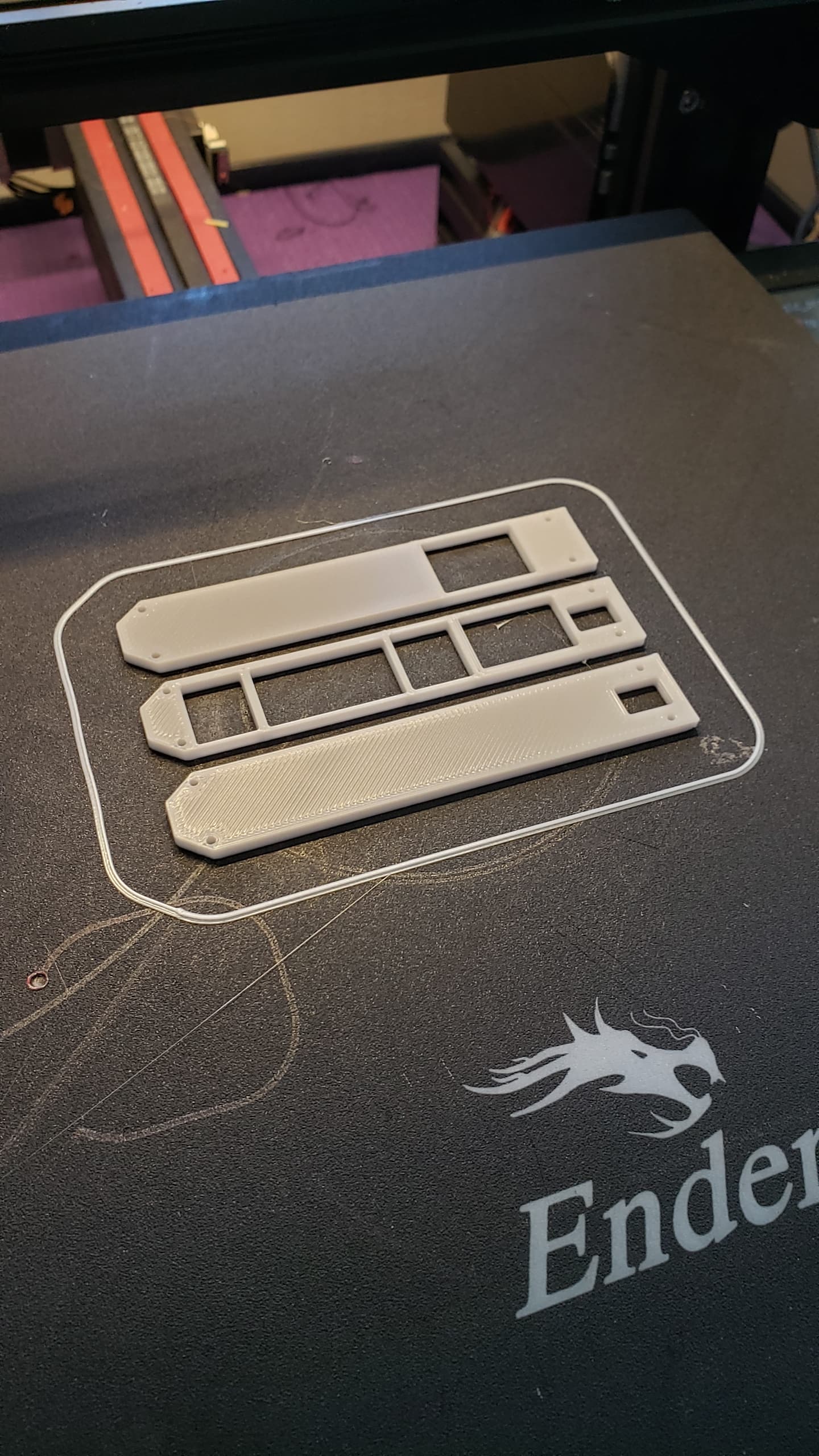
found it (old-probe), and modeled up the new one… , attached is the STL, G-code & Fcad file.
enjoy , I’ll print one and post a pic.
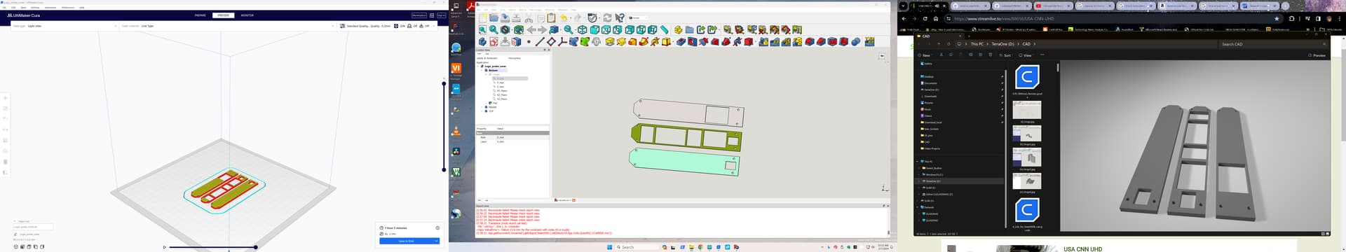
Logic_probe_cover.zip (331.5 KB)
Updated…ZIP
Moved screw holes and add another cut out for power leads, Looks good , I’ll try to print it in RED and the top piece in clear later also.
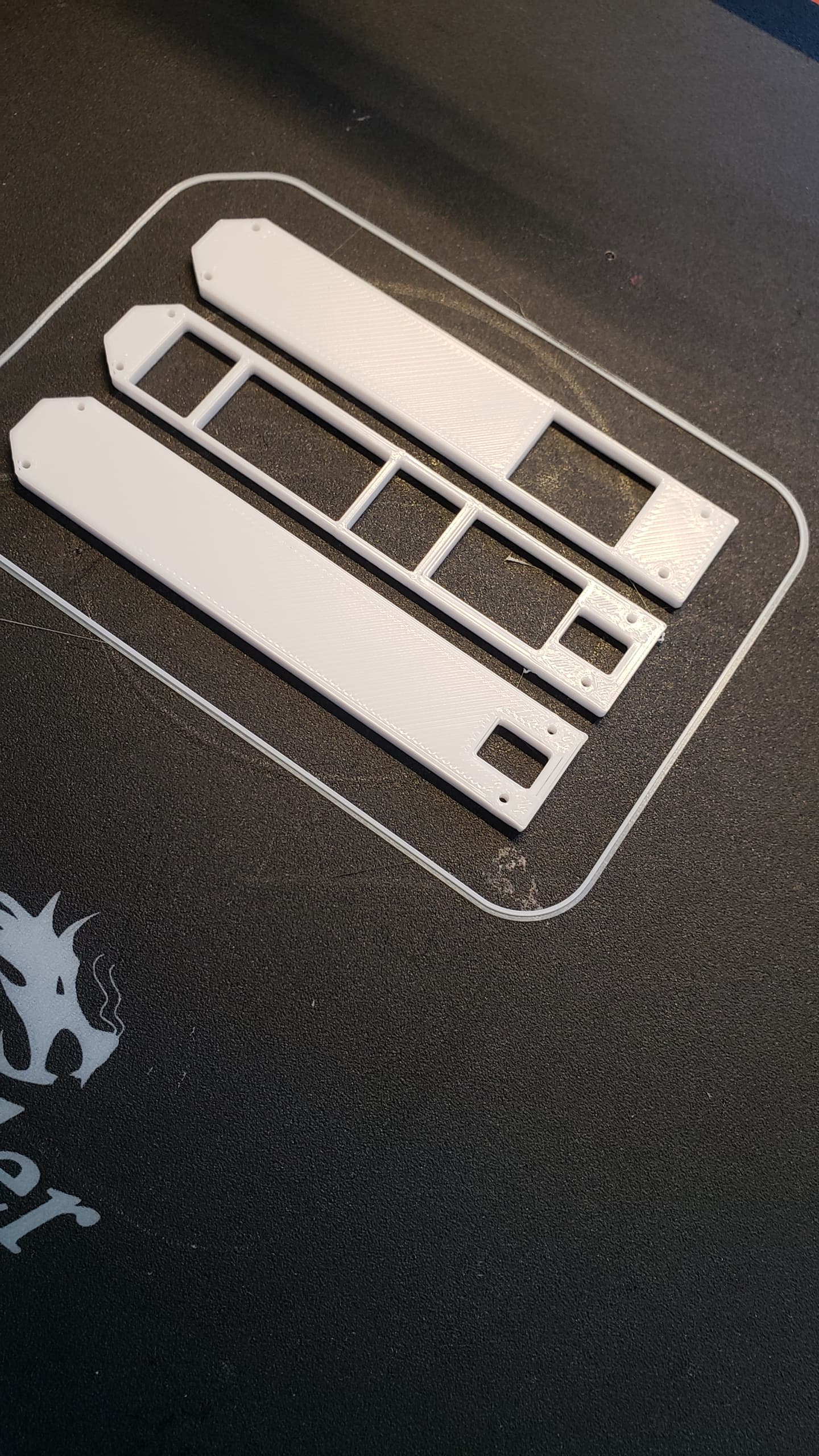
Update … The Red looks Nice.

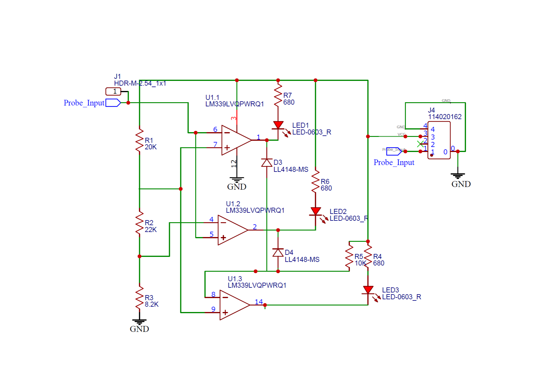
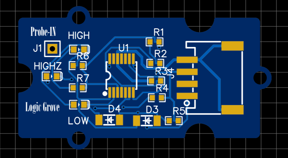
So I imported, the schematic. and converted it to a GROVE Platform.
Zip file has everything you would need to order one from , Fusion Service or JLPCB…
Enjoy.
HTH
GL ![]() PJ
PJ
![]()

The should include it with the KIT ![]()

zip has , BOM, Gerber, Pick&Place and schematic as well as the pictures
HTH
GL ![]() PJ
PJ
![]()
![]()
Grove_Logic_Probe.ZIP (468.9 KB)
How’d your project go? Were you able to successfully use the JTAGS as GPIO pins?
HI there,
Absolutely were able to, You can too try the code for yourself It works.
HTH
Gl ![]() Pj
Pj ![]()