Good day all.
I am currently debugging some hardware which has been built by a student.
I am writing the code. The hardware has D5 and D6 as set as inputs with pull up enabled, no external resistors.
pinMode(D5, INPUT_PULLUP);
pinMode(D6, INPUT_PULLUP);
D5 and D6 monitor to signal lines, each driven by an optocoupler.
D5 and D6 are each attached to interrupts.
attachInterrupt(D5, d5ISR, RISING);
attachInterrupt(D6, d6ISR, FALLING);
Each ISR handles the interrupts as normal, routine for D5 shown, d5Flag is a defined as bool.
The counter (uint32_t d5Counter = 0;) simply keeps track of the number of events…
void IRAM_ATTR d5ISR()
{
  d5Flag = true;
  d5Counter++;
}
What I find is that for each triggered event, when the counts are read back, the counts are increment by large amounts, varying from 100s to 1000s, all depending on the period between each interrupt event.
The edge inputs to D5 and D6 are clean and fast. No noise.
This has got me stumped. Are there any caveats in using these pins for interrupts. If so, I will have to modify the PCBs.
Regards and thanks.
Hi there,
Can you try using the GPIO pin numbers instead?
give it a go,
HTH
GL  PJ
PJ
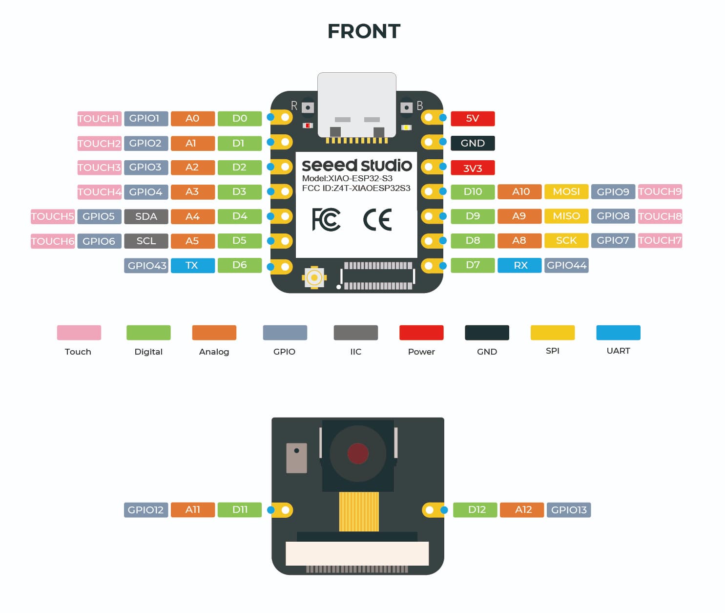
ie. GPIO (06), GPIO (43)
I’ll try your suggestion later today.
To confirm pin functions as D5 and D6, I placed a normal switch to ground and tested with a basic
digitalRead(D5);
operation, and this worked as expected for the definition, same for D6.
Cheers.
I believe that I have solved the problem.
Changing the D5 and D6 definitions to GPIO definitions did NOT solve the issues at hand.
I systematically shut down other modules that were running to try to isolate the cause.
Nothing was resolved until I turned off in code the HTTP requests, effectively shutting down the periodic 5 second WiFi activities. No HTTP requests, no extraneous IRQ events.
Further tests and with the use of a DSO, I found that the WiFi bursts were creating a multitude of IRQ events, quite possibly due to the weak on chip PULL_UP resistors not being able to withstand the induced interference from the WiFi signal. The 5V and 3V3 supply rails all appear to be clean, as they have additional filtering added on the PCB.
Must admit, this is the first time I have ever seen this happen. The board will be modified tomorrow with the addition of strong PULL_UP resistors being fitted, plus some signal filtering added to the opto isolators outputs.
Cheers.
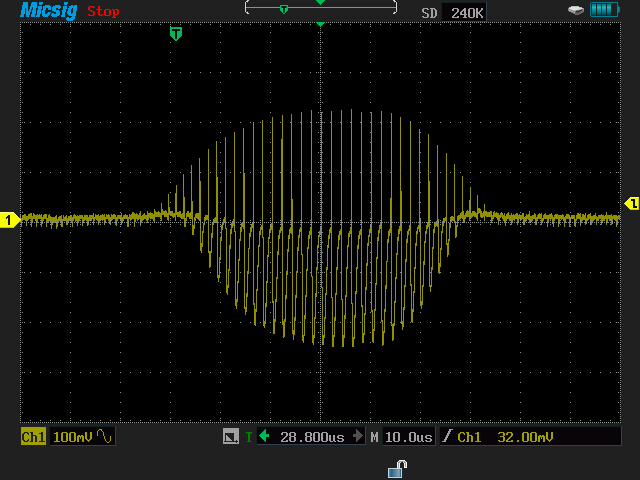
Ok. I’ve come back to this problem, still no resolution, and decided to do some real electronic analysis. I managed to get a scope trace of the interrupt pin currently in question, D5.
The pin is pulled high with the following code snippet,
pinMode(D5, INPUT_PULLUP);
WiFi is enabled and connected using the default examples provided by ESP Arduino libraries. The interrupt signal is a falling edge that occurs very randomly, between 0 and 5 times an hour. So not that often.
The scope trace shows what sits on top of the the 3.3V rail voltage of D5. Essentially the pull-up voltage for the pin. The WiFi interacts every 5secs. The interrupt event count increments by 10 - 100 counts for every WiFi event (essentially being polled by a server)
This is obviously the fault which contributes to the errors that I have been experiencing.
The same occurs for D6 when the connections are swapped.
Now back to the lab.
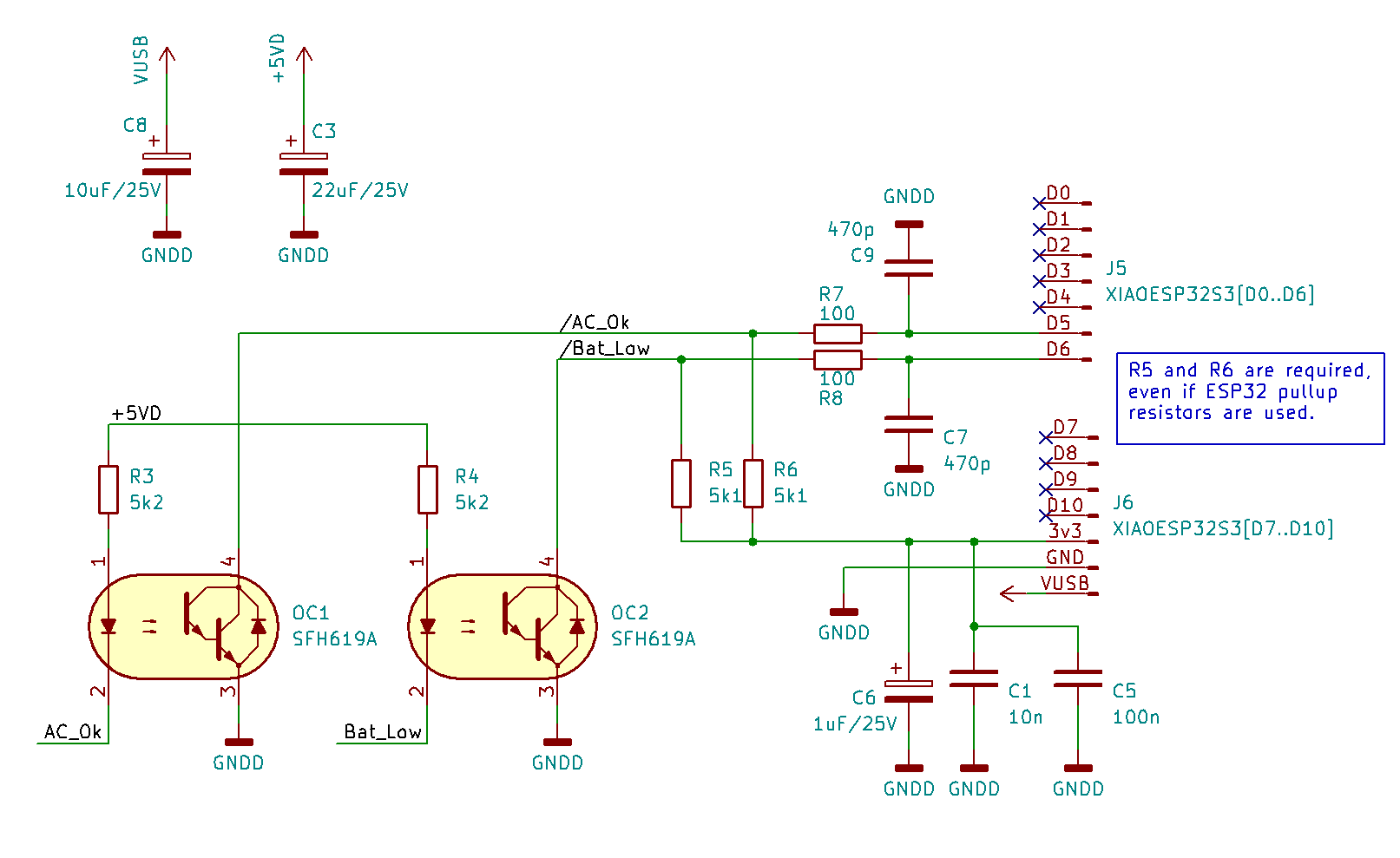
Finally, a working solution. The fix has now been running for over 24 hours with no false triggers. The one critical item of importance that the students did not take into account (nor did I) is that the GPIO pins are somewhat high impedance, so very susceptible to any RF noise, WiFi signals being the issue here.
So, whether you have internal pull-ups enabled or not, the following circuit acts as a low impedance load and includes some RF filtering. The opto couplers are required due to the differing logic voltages on the main PCB. I’ll run this circuit over the next few days to fully assess. Then if all is well, this will be added to the ESP32 pool of bug fixes.
Cheers.
External Pull-ups do work Nice, opto isolators too,cool solution.
GL PJ