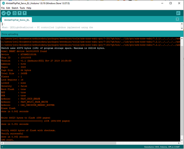
After reading a bit it seems as though a sketch made for the Nano with Atmega328P cannot work on the XIAO based on the SAMD21?
Is it possible to port the Nano sketch to the XIAO somehow? Here is the program that works fine with the Nano.
#include <Servo.h>
Servo myservo;

int pos = 3;    // variable to store the servo position

volatile int ledPin   = 10;      // the pin that the LED is attached to, needs to be a PWM pin.
volatile int servoPin = 9;      // the pin that the servo signal is attached to, needs to be a PWM pin.
int brightness = 0;

enum devices
{
  FLAT_MAN_L = 10,
  FLAT_MAN_XL = 15,
  FLAT_MAN = 19,
  FLIP_FLAT = 99
};

enum motorStatuses
{
  STOPPED = 0,
  RUNNING
};

enum lightStatuses
{
  OFF = 0,
  ON
};

enum shutterStatuses
{
  UNKNOWN = 0, // ie not open or closed...could be moving
  CLOSED,
  OPEN
};


int deviceId = FLIP_FLAT;
int motorStatus = STOPPED;
int lightStatus = OFF;
int coverStatus = UNKNOWN;

#include <Adafruit_DS3502.h>

Adafruit_DS3502 ds3502 = Adafruit_DS3502();
/* For this example, make the following connections:
    * DS3502 RH to 5V
    * DS3502 RL to GND
    * DS3502 RW to the pin specified by WIPER_VALUE_PIN
*/

#define WIPER_VALUE_PIN A0
/*Do NOT connect RW to A0 when an external power source (>5v) is connected to the DS3502.  That could damage the A0 pin and board.
*/

void setup()
{
  // initialize the serial communication:
  Serial.begin(9600);
  // initialize the ledPin as an output:
  pinMode(ledPin, OUTPUT);
  digitalWrite(ledPin, LOW);
  myservo.attach(servoPin);
  myservo.write(pos);              // tell servo to go to position in variable 'pos'
  ds3502.begin();
}

void loop()
{
  handleSerial();
}


void handleSerial()
{
  if( Serial.available() >= 5 )  // all incoming communications are fixed length at 6 bytes including the \n
  {
    char* cmd;
  char* data;
    char temp[10];

    int len = 0;

    char str[20];
    memset(str, 0, 20);

  // I don't personally like using the \n as a command character for reading.
  // but that's how the command set is.
    Serial.readBytesUntil('\n', str, 20);

  cmd = str + 1;
  data = str + 2;

  // useful for debugging to make sure your commands came through and are parsed correctly.
    if( false )
    {
      sprintf( temp, "cmd = >%s%s;", cmd, data);
      Serial.println(temp);
    }


    switch( *cmd )
    {
    /*
    Ping device
      Request: >P000\n
      Return : *Pii000\n
        id = deviceId
    */
      case 'P':
      sprintf(temp, "*P%d000\n", deviceId);
      Serial.print(temp);
      break;

      /*
    Open shutter
      Request: >O000\n
      Return : *Oii000\n
        id = deviceId

      This command is only supported on the Flip-Flat!
    */
      case 'O':
      sprintf(temp, "*O%d000\n", deviceId);
      SetShutter(OPEN);
      Serial.print(temp);
      break;


      /*
    Close shutter
      Request: >C000\n
      Return : *Cii000\n
        id = deviceId

      This command is only supported on the Flip-Flat!
    */
      case 'C':
      sprintf(temp, "*C%d000\n", deviceId);
      SetShutter(CLOSED);
      Serial.print(temp);
      break;

    /*
    Turn light on
      Request: >L000\n
      Return : *Lii000\n
        id = deviceId
    */
      case 'L':
      sprintf(temp, "*L%d000\n", deviceId);
      Serial.print(temp);
      lightStatus = ON;
      digitalWrite(ledPin, HIGH);
      break;

    /*
    Turn light off
      Request: >D000\n
      Return : *Dii000\n
        id = deviceId
    */
      case 'D':
      sprintf(temp, "*D%d000\n", deviceId);
      Serial.print(temp);
      lightStatus = OFF;
      digitalWrite(ledPin, LOW);
      break;

    /*
    Set brightness
      Request: >Bxxx\n
        xxx = brightness value from 000-255
      Return : *Biiyyy\n
        id = deviceId
        yyy = value that brightness was set from 000-255
    */
      case 'B':
      brightness = atoi(data);
      setPanelBrightness(brightness);

      sprintf( temp, "*B%d%03d\n", deviceId, brightness );
      Serial.print(temp);
        break;

    /*
    Get brightness
      Request: >J000\n
      Return : *Jiiyyy\n
        id = deviceId
        yyy = current brightness value from 000-255
    */
      case 'J':
        sprintf( temp, "*J%d%03d\n", deviceId, brightness);
        Serial.print(temp);
        break;

    /*
    Get device status:
      Request: >S000\n
      Return : *SidMLC\n
        id = deviceId
        M  = motor status( 0 stopped, 1 running)
        L  = light status( 0 off, 1 on)
        C  = Cover Status( 0 moving, 1 closed, 2 open)
    */
      case 'S':
        sprintf( temp, "*S%d%d%d%d\n",deviceId, motorStatus, lightStatus, coverStatus);
        Serial.print(temp);
        break;

    /*
    Get firmware version
      Request: >V000\n
      Return : *Vii001\n
        id = deviceId
    */
      case 'V': // get firmware version
      sprintf(temp, "*V%d001\n", deviceId);
      Serial.print(temp);
      break;
    }

  while( Serial.available() > 0 )
    Serial.read();

  }
}

void SetShutter(int val)


{
  if( val == OPEN && coverStatus != OPEN )
  {
    for (int angle = 3; angle <= 180; angle+=1)
    {
      myservo.write (angle);
      delay (70);

    }
    coverStatus = OPEN;
    // TODO: Implement code to OPEN the shutter.
  }
  else if( val == CLOSED && coverStatus != CLOSED )
  {
    for (int angle = 180; angle > 3; angle-=1)
    {
      myservo.write (angle);
      delay (70);

    }
    coverStatus = CLOSED;
    // TODO: Implement code to CLOSE the shutter
  }
  else
  {
    // TODO: Actually handle this case
    coverStatus = val;
  }

}

void setPanelBrightness( int brightness ){
  // alnitak has values from 0-100 for brightness.
  // ds3502 supports 0-127 so these need to get mapped.

  /*  this makes the assumption that 127 is "max resistance"
   *  and "max resistance" is the dimmest value.
   *  if that is not the case then the map needs to be:
   *  int val = map(brightness, 0, 100, 0, 127);
   *  EDIT: apparently the max resistance is half of 127 or 63.
   */

  int val = map(brightness, 0, 100, 0, 63);
  ds3502.setWiper(val);
}

