I don’t have the PPK2 with me but it seems the flash can accept the command regardless of QSPI or SPI mode.
#include <Adafruit_SPIFlash.h>

/*I have added Xiao flash chip to library so no need to define in the sketch*/


/*Map flash as QSPI, comment out below line if choose to map as SPI*/
//Adafruit_FlashTransport_QSPI flashTransport;


/*Map flash as custom SPI, comment out below 2 lines if choose to map as QSPI*/
SPIClass SPI_2(NRF_SPIM2, PIN_QSPI_IO1, PIN_QSPI_SCK, PIN_QSPI_IO0);
Adafruit_FlashTransport_SPI flashTransport(PIN_QSPI_CS, SPI_2);


Adafruit_SPIFlash flash(&flashTransport);


uint8_t three_byte_response[3] = {0};

void setup()
{
  Serial.begin(115200);
  while ( !Serial ) delay(10);
  flash.begin();

  /*Read ID*/
  flashTransport.readCommand(0x9F, three_byte_response, 3);
  Serial.print("Manufacture and Device ID before Sleep = ");
  for (uint8_t k = 0; k < 3; k++)
  {
    Serial.print(three_byte_response[k], HEX);
    Serial.print(" ");
  }
  Serial.println();
  /*Clear response buffer*/
  memset(three_byte_response, 0, sizeof(three_byte_response));

  /*Enter deep sleep for 3s*/
  flashTransport.runCommand(0xB9);
  Serial.println("Flash enters deep sleep for 3s.");
  delay(3000);

  /*Release from deep sleep*/
  flashTransport.runCommand(0xAB);
  Serial.println("Flash wakes up.");

  /*Read ID again*/
  flashTransport.readCommand(0x9F, three_byte_response, 3);
  Serial.print("Manufacture and Device ID after Sleep = ");
  for (uint8_t k = 0; k < 3; k++)
  {
    Serial.print(three_byte_response[k], HEX);
    Serial.print(" ");
  }
  Serial.println();
}

void loop()
{
  // nothing to do
}
Tried QSPI and SPI modes with the Adafruit library and the SerialFlash library.
Both libraries could initialize the Flash and read the chip ID, but they did not respond to commands even though there were “0xB9” and “0xAB” signals on the SPI bus.
Then, when I use the SPI.transfer() function, it responds to the command as I want and I can use DeepPowerDown mode. Also, oddly enough, if the time between “enter” and “release” is short (less than 200mS), DPD mode works even with the Adafruit library.
I am almost out of my depth. I think this will be a theme to keep.
I am experimenting with external Flash.
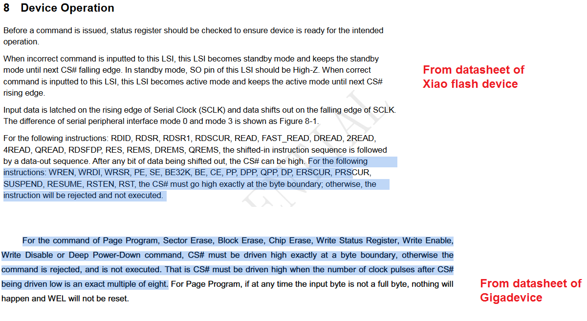
The value changes to HIGH or LOW depending on the bus state, but when the command “0xB9” or “0xAB” is output, WP# is definitely HIGH and there should be no problem.
I think the difference is that when SPI.transfer() is used, WP# is definitely fixed to HIGH by digitalWrite().
The QSPI driver was released by Nordic but it cannot wake the flash up after deep sleep, as stated here.
The driver used by Adafruit core was based on earlier Nordic SDK and it will be not fixed since Nordic has migrated the SDK to a new version nRF Connect.
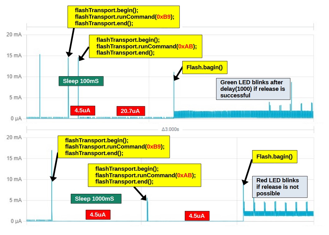
It took some time to re-experiment and summarize the data, then I found the following
runCommand() can enter but cannot release. However, if the sleep time is less than 200mS, it can be released.
SPI.transfer() can enter and release with no problem.
My hypothesis is that XIAO sends “0x05” to Flash in DeepPowerDown mode and waits for a reply, but Flash ignores it and times out, as described in post 17.
I will now read the Nordic information more carefully.
Thanks MS for the elaboration.
Never have imagined that a few years old library still got a bunch of basic operation issues. Anyway a hobby is both frustration and fun hahaha.
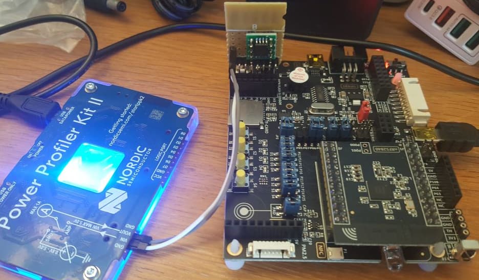
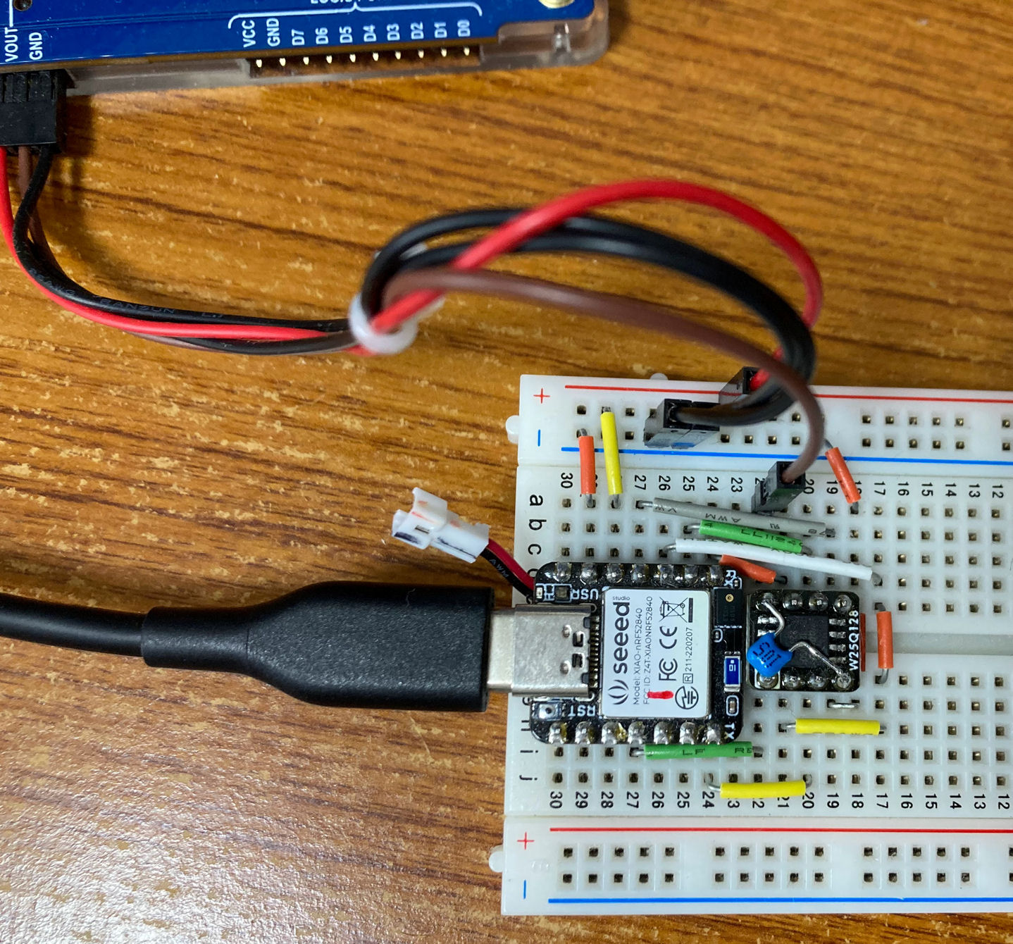
The external Flash is W25Q128JV (Winbond), connected via SPI, with unused WP and HOLD pins pulled up.
The current flowing into the VCC pin is measured.
The command sequence is:
flash.begin() -->enter–>release–>flash.begin().
Using SPI.transfr(),
5.7uA–>0.26uA–>5.7uA–>5.7uA
Using runCommand(),
5.7uA–>300uA–>600uA–>5.7uA
External Flash does not seem to execute runCommand() correctly.
“0x66”,“0x99” is used instead of “0xAB”, the result is the same as 2.
As you have stated previously, you visually noticed correct commands sent to the flash regardless of SPI.transfer or runCommand.
I read the JEDEC ID before & after sleep/release and the flash behaved the same regardless of the 2 methods. This experiment makes me think the flash sleeps and wakes properly.
However it is really hard to explain the difference in its current consumption.
In post 6, I did not know how to release the internal Flash from DeepPowerDown mode (DPD), so I used it without DPD. As a result, the current during the sleep period only dropped to 26uA.
Since post 7, we have discussed how to release from DPD, and I have confirmed that Flash will release from DPD using SPIClass.
Also, the BME280 breakout board had a mounted LDO and level shifter, which consumed current, so I changed to a breakout board that did not have these mounted.
With these measures, I was able to reduce the sleep current to 5uA. I think this value is almost the limit of the project using SystemONSleep mode and RTOS.
I observed the waveforms of the external Flash when runCommand() is issued: In the case of the QSPI connection, “0x05” is added and the status register is read, as in “0x05”+“0xB9” and “0x05”+“0xAB”. In the case of SPI connection, however, “0x05” is not added and only “0xB9” and “0xAB” are observed.
In both cases, the enter or release command will cause a large current to flow through the external Flash. I have no idea why the behavior is different between onboard Flash and external Flash.
Also, I am wondering if it is possible to use QSPI connection for the external Flash since the onboard Flash is already connected to QSPI.
It seems only one instance of QPSI is supported but 3 instances for SPI.
However for those single byte commands, they are transmitted as standard SPI signals regardless of SPI.transfer or runCommand.
0x05 seems to be querying if the flash is busy or not and should not cause adverse effects.
Congratulations to your latest achievement in the current consumption. Although there are still unknown questions, your example provides a workaround to drive nRF52840 to its extreme performance, well done !!
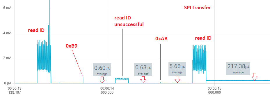
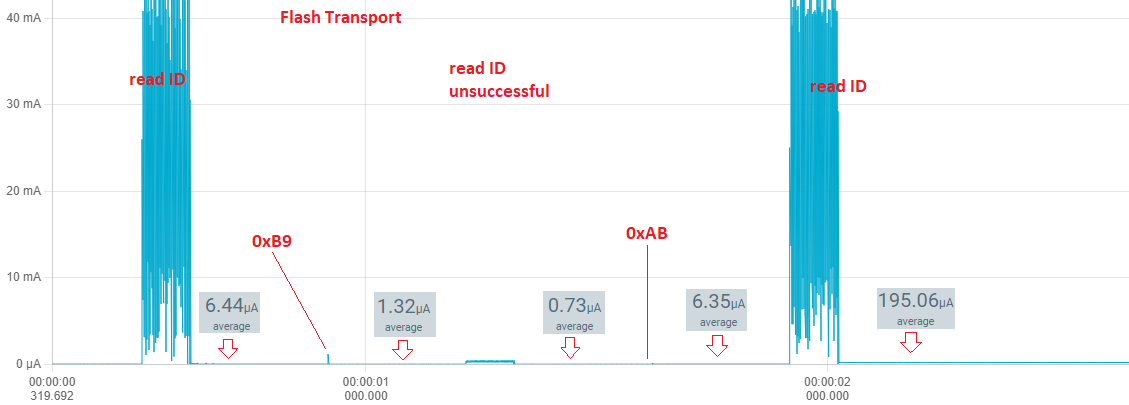
I eventually got a development board and an external flash. However I did not see obvious difference sending the deep sleep and wake up commands with SPI transfer and Flash Transport. The flash seemed to sleep and wake up properly. However the working current using SPI transfer seemed to be much lower. The graphs below showed the current passing through the external flash chip.
I did a reproduction experiment.
As you can see in the attached data, Enter and Release seemed to be executed properly and the current was almost the same as your measurements. However, there was a big difference in the current value after the third read ID. Also, my external Flash has a capacitor mounted between VCC and GND, so there seems to be a difference in the current waveform.
Thanks MS for the re-test. Indeed the waveforms of our measurements are very much different. I have noticed long time ago that your measurements were always less noisy. Are you always using the highest sampling rate for your measurements?
The increase of current after reading the ID the 3rd time is a mystery. I think your measurement shows a more reasonable value. I shall imitate your setup and retry.