Will try this code.
I found interesting the disconnection of used pins.
Also a different library to enter flash sleep mode.
My hardware is only the xiao, with a 3.6v lipo cell.
The hx711 is actually disconnected
ALso , worth noting is in the WakeUp interrupt, Using the EDGE (Rising/Falling) takes more power than using the LEVEL (LOW/HIGH) as the trigger. Just FYI
As you were.
GL PJ
Every little bit helps. @msfujino could write a thesis on this stuff so READ it all and follow his lead!
For the Bow, Tie on this one…
I found this Tap to wake, well documented, and Tests very well. Not sure where it came from ? But works very well.
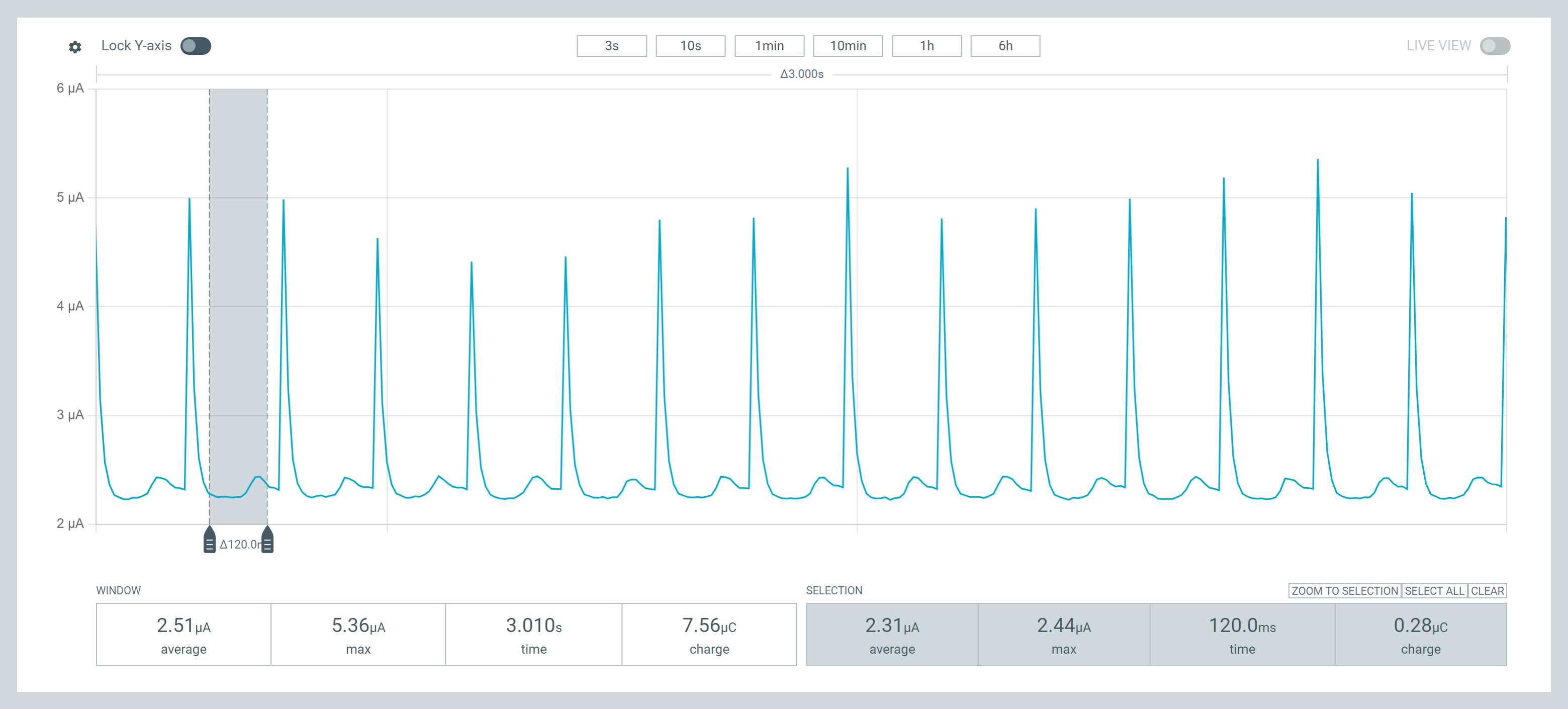
9.3uA
tap to wake.
#include <Adafruit_SPIFlash.h>
#include <LSM6DS3.h>
#include <nrf52840.h>
#include <Wire.h>

Adafruit_FlashTransport_QSPI flashTransport;
LSM6DS3 myIMU; // Default is I2C mode

void QSPIF_sleep(void)
{
  flashTransport.begin();
  flashTransport.runCommand(0xB9);
  flashTransport.end();
}

void setupWakeUpInterrupt()
{
  // Start with LSM6DS3 in disabled to save power
  myIMU.settings.gyroEnabled = 0;
  myIMU.settings.accelEnabled = 0;

  myIMU.begin();

  // Set up the accelerometer for Wake-up interrupt.
  // Per the application note, use a two step set up to avoid spurious interrupts
  // Set up values are from the application note, and then adjusted for minimum power

  myIMU.writeRegister(LSM6DS3_ACC_GYRO_WAKE_UP_DUR, 0x00); // No duration
  myIMU.writeRegister(LSM6DS3_ACC_GYRO_WAKE_UP_THS, 0x02); // Set wake-up threshold
  myIMU.writeRegister(LSM6DS3_ACC_GYRO_TAP_CFG1, 0x80);    // Enable interrupts and apply slope filter; latch mode disabled
  myIMU.writeRegister(LSM6DS3_ACC_GYRO_CTRL1_XL, 0x70);    // Turn on the accelerometer
                                                           // ODR_XL = 833 Hz, FS_XL = ±2 g
  delay(4);                                                // Delay time per application note
  myIMU.writeRegister(LSM6DS3_ACC_GYRO_CTRL1_XL, 0xB0);    // ODR_XL = 1.6 Hz
  myIMU.writeRegister(LSM6DS3_ACC_GYRO_CTRL6_G, 0x10);     // High-performance operating mode disabled for accelerometer
  myIMU.writeRegister(LSM6DS3_ACC_GYRO_MD1_CFG, 0x20);     // Wake-up interrupt driven to INT1 pin

  // Set up the sense mechanism to generate the DETECT signal to wake from system_off
  // No need to attach a handler, if just waking with the GPIO input.
	pinMode(PIN_LSM6DS3TR_C_INT1, INPUT_PULLDOWN_SENSE);

  return;
}

void setup()
{
  // Serial.begin(9600);
	 // delay(3000); //relax...
   // Serial.println();
	 // Serial.println("Processor came out of reset.\n");
  pinMode(LED_RED, OUTPUT);
  pinMode(LED_GREEN, OUTPUT);

  digitalWrite(LED_RED, HIGH);
  digitalWrite(LED_GREEN, HIGH);

  QSPIF_sleep();

  // Flash green to see power on, reset, and wake from system_off
  digitalWrite(LED_GREEN, LOW);
  delay(1000);
  digitalWrite(LED_GREEN, HIGH);;

  // Minimizes power when bluetooth is used
  NRF_POWER->DCDCEN = 1;
}

void loop()
{
  // FreeRTOS will automatically put the system in system_on sleep mode here
  delay(10000); // Measure idle loop power during this period

  // Flash red before system_off sleep
  digitalWrite(LED_RED, LOW);
  delay(500);
  digitalWrite(LED_RED, HIGH);;

  // Setup up double tap interrupt to wake back up
  setupWakeUpInterrupt();

  // Execution should not go beyond this
  NRF_POWER->SYSTEMOFF = 1;
}
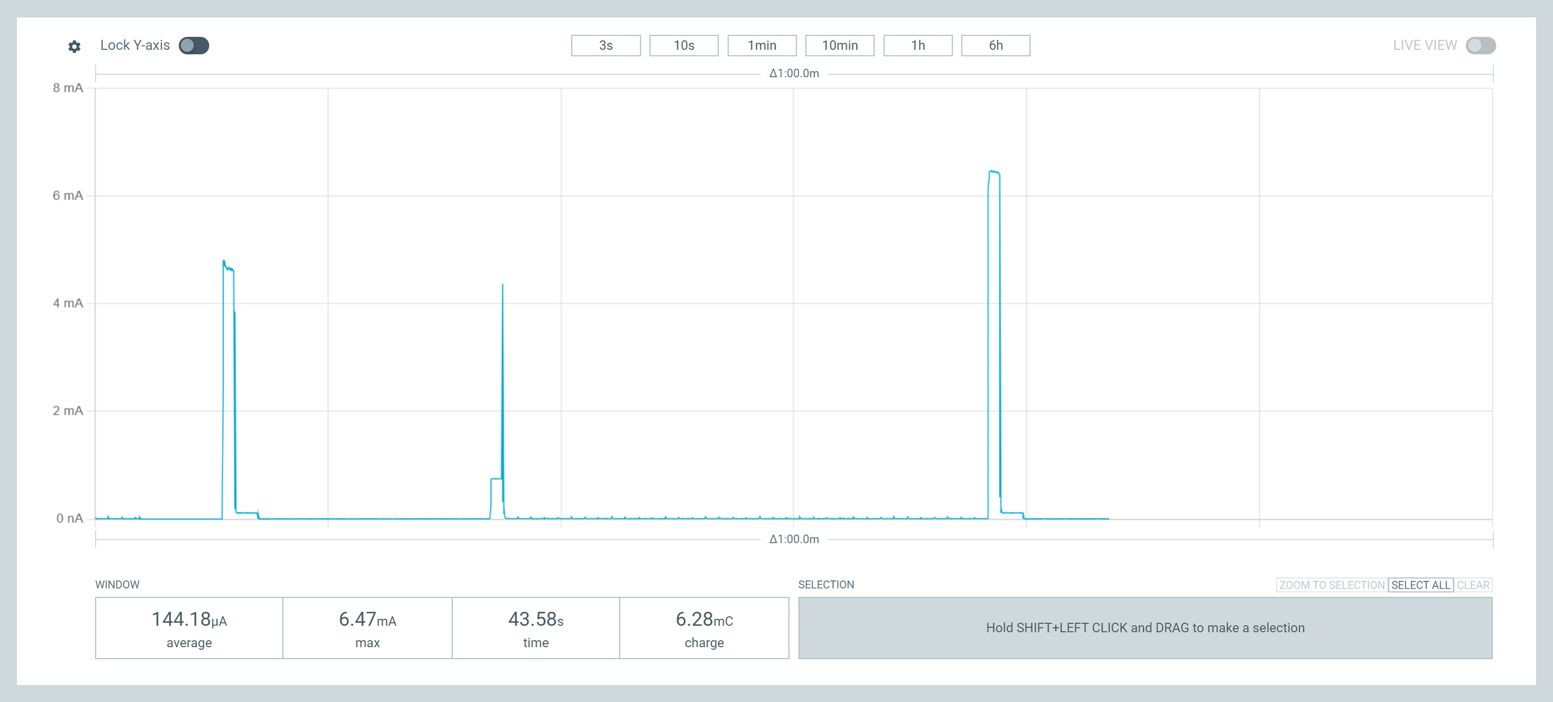
I found some days ago this same single tap wakeup and already applied , it gave me 10uA in system off.
When integrated in my sw , I got 80uA, which is not bad.
But today you opened my mind with the disconnectPin() function.
I started disconnecting D7 D8 and D9 which I used to control the HX711, and the current reduced to 70uA.
Then I remembered that I am reading the battery with the library Xiao_NRF52840_Battery , which uses 3 pins to read and control the battery circuitry.
I disconnected PIN_VBAT , BAT_CHARGE_STATE and VBAT_ENABLE.
And guess, now I’m getting 10uA !
Very interesting.
My measurements before / after disconnecting PiN_VBAT , BAT_CHARGE_STATE and VBAT_ENABLE were 70uA and 10uA.
A big difference for just a voltage divider.
I will investigate further to understand the individual current contribution for each pin.
According to the schematic, BAT_CHARGE_STATE consumes a large current as it drives the green LED. It should be set to an input pin and pulled up. Please refer to SleepCurrent_VbatEnable.zip attached to the link.
pinMode(CHG, INPUT_PULLUP); // sleep current increases significantly without pull-up