Yes, This works however as You can see it’s "horse-shoe’s and Hand-Grenades’ accurate(close-enough) but I hope they come with something that doesn’t require this low level maintenance B.S. And BTW “adafruit” product software data and doc’s eat their lunch compared to Seeed engineering(should rename it to licensing dept.) but I digress,
I do this on any systems I’m building with this ISSUE; It’s a “WORK-AROUND”
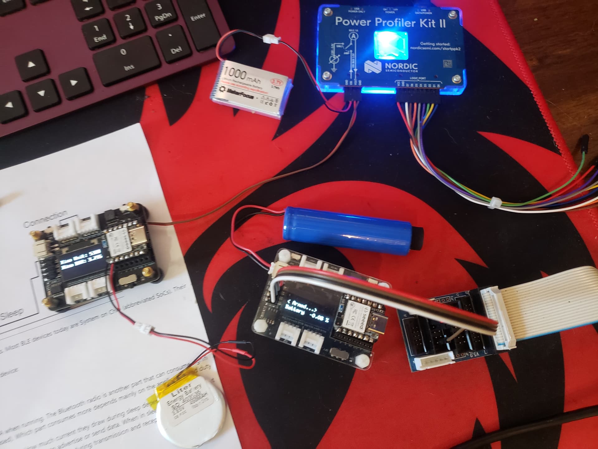
I can test that it tracks some what with the PPK2 as the source 2.2v to 3.85 range tests always off by about .6 ish.
I ,
- Delete “pin_arduino.h” and “variant.cpp” in directry “\2.9.1\variants\SEEED_XIAO_NRF5284” and “\2.9.1\variants\SEEED_XIAO_NRF5284_SENSE”,
then copy “pin_arduino.h” and “variant.cpp” from the unzip folder. - RESTART Arduino IDE
| WARNING!!!. |
Choose board, compile and test it.
HTH
GL
I have two expansion units both work as advertised, albeit the battery can’t be read in that? LOL
Fresh Battery…OK
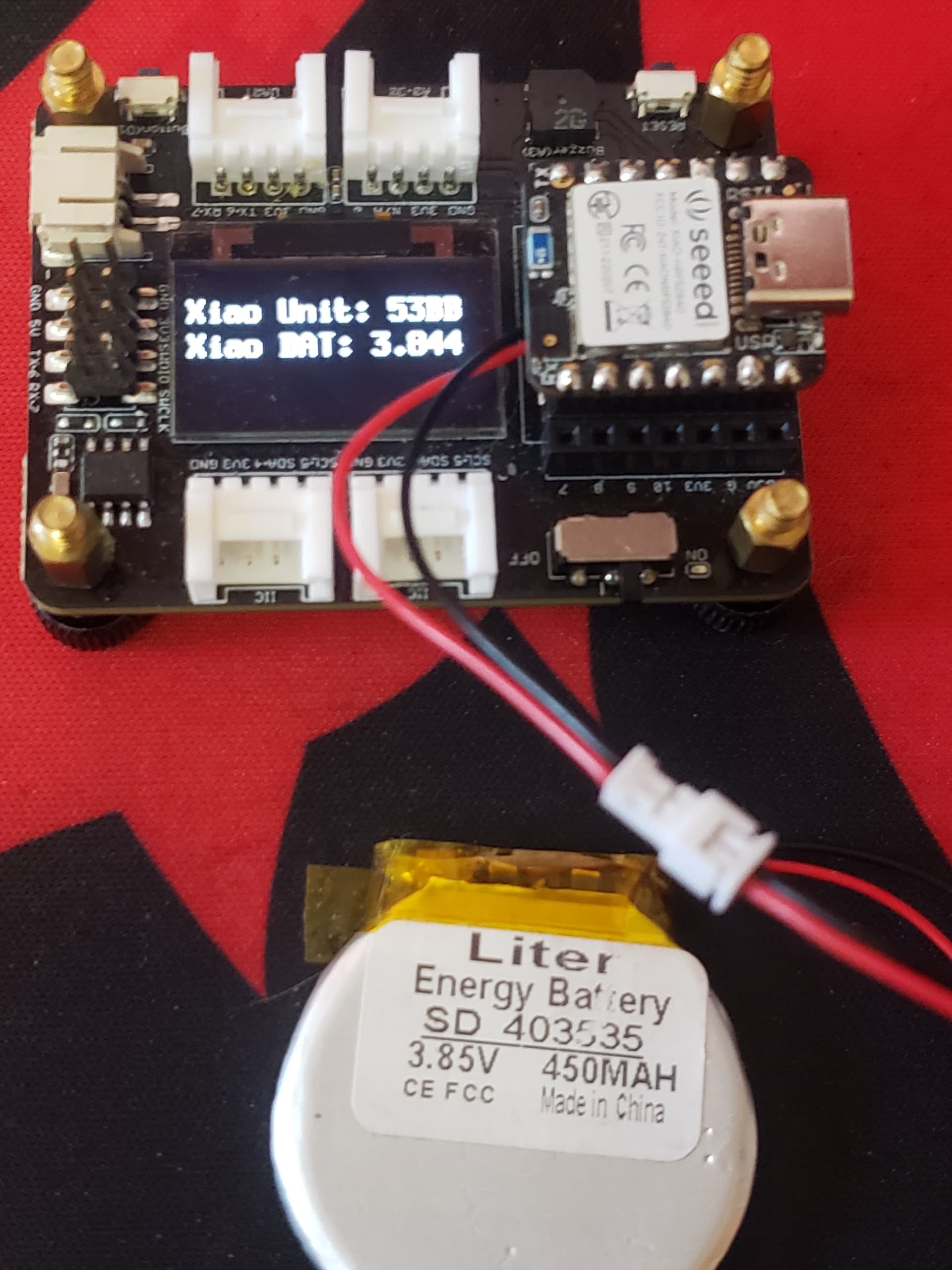
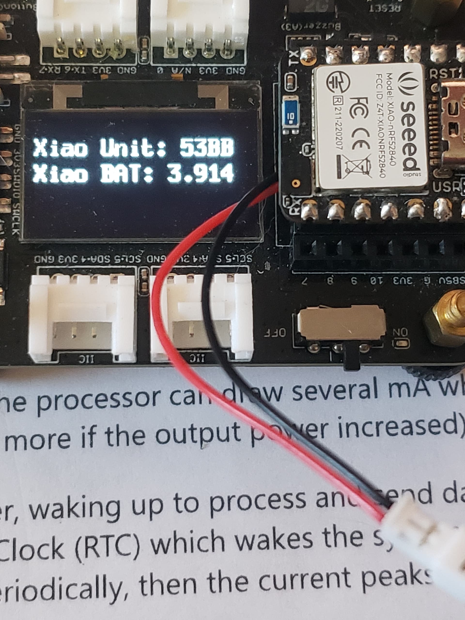
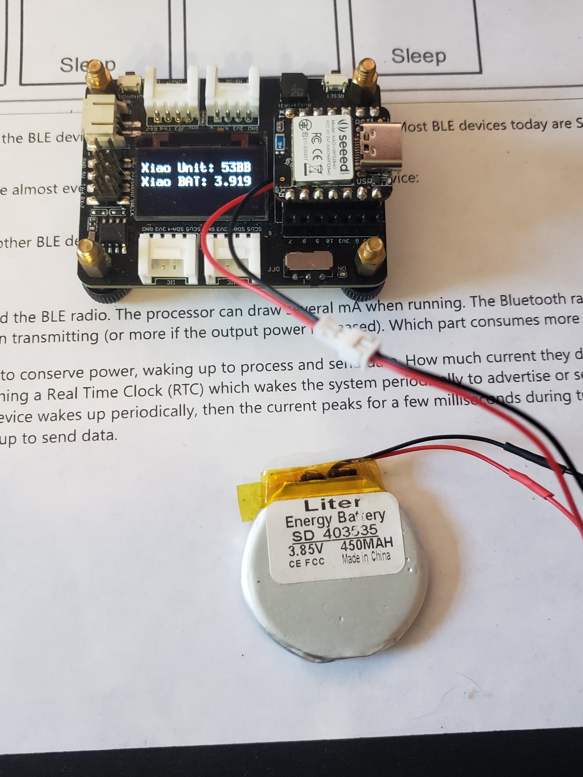
High reading a TAD
maybe I expect too much? or I’m doing it wrong
Both work currently and I do think there’s room for improvement, It’s expansion/development pick a lane for goodness sake also.
Can’t beat the Footprint though… A+
#include "LSM6DS3.h"
#include "Wire.h"
LSM6DS3 myIMU(I2C_MODE, 0x6A); // IMU
#define int1Pin PIN_LSM6DS3TR_C_INT1

const int ledPin = LED_BUILTIN; // set ledPin to on-board LED

uint8_t interruptCount = 0; // Amount of received interrupts
uint8_t prevInterruptCount = 0; // Interrupt Counter from last loop

void setup() {
  Serial.begin(9600);
  while ( !Serial ) delay(10);   // for nrf52840 with native usb
  pinMode(ledPin, OUTPUT); // use the LED as an output

  Serial.println("Hello, I am awake!");
  myIMU.settings.gyroEnabled = 0; // Gyro currently not used, disabled to save power
  if (myIMU.begin() != 0) {
    Serial.println("IMU error");
  } else {
    Serial.println("IMU OK!");
  }

  setupDoubleTapInterrupt();

  pinMode(int1Pin, INPUT);
  attachInterrupt(digitalPinToInterrupt(int1Pin), int1ISR, RISING);
}

void loop() {
  setLED(false);
  Serial.print("Interrupt Counter: ");
  Serial.println(interruptCount);

  if (interruptCount > prevInterruptCount) {
    Serial.println("Interrupt received!");
  }
  prevInterruptCount = interruptCount;

  if (interruptCount >= 3) {
    // Trigger System OFF after 5 interrupts
    goToPowerOff();
  }

  delay(500);
}

void goToPowerOff() {
  Serial.println("Going to System OFF");
  setLED(true);
  setupDoubleTapInterrupt();
  delay(1000); // delay seems important to apply settings, before going to System OFF
  //Ensure interrupt pin from IMU is set to wake up device
  nrf_gpio_cfg_sense_input(digitalPinToInterrupt(int1Pin), NRF_GPIO_PIN_PULLDOWN, NRF_GPIO_PIN_SENSE_HIGH);
  delay(2000);// Trigger System OFF
  NRF_POWER->SYSTEMOFF = 1;
}

void setupDoubleTapInterrupt() {
  uint8_t error = 0;
  uint8_t dataToWrite = 0;

  // Double Tap Config
  myIMU.writeRegister(LSM6DS3_ACC_GYRO_CTRL1_XL, 0x60); //* Acc = 416Hz (High-Performance mode)// Turn on the accelerometer
  // ODR_XL = 416 Hz, FS_XL = 2g
  myIMU.writeRegister(LSM6DS3_ACC_GYRO_TAP_CFG1, 0x8E);// INTERRUPTS_ENABLE, SLOPE_FDS// Enable interrupts and tap detection on X, Y, Z-axis
  myIMU.writeRegister(LSM6DS3_ACC_GYRO_TAP_THS_6D, 0x85);// Set tap threshold 8C
  myIMU.writeRegister(LSM6DS3_ACC_GYRO_INT_DUR2, 0x7F);// Set Duration, Quiet and Shock time windows 7F
  myIMU.writeRegister(LSM6DS3_ACC_GYRO_WAKE_UP_THS, 0x80);// Single & double-tap enabled (SINGLE_DOUBLE_TAP = 1)
  myIMU.writeRegister(LSM6DS3_ACC_GYRO_MD1_CFG, 0x08);// Double-tap interrupt driven to INT1 pin
}

void int1ISR() {
  interruptCount++;
}

  void setLED(bool on)
  {
  // data = 1 -> LED = On
  // data = 0 -> LED = Off
  digitalWrite(LED_BUILTIN, on ? HIGH : LOW);
  }
The Hint is the charge LED… It’s illuminated when sleeping(with no battery connected), USB only. as before the variants patch no battery voltage is readable and so also After taping to wake up and fully on, No battery voltage is readable? Useless . Terrible for a battery powered chip.
I’m disappointed.