XIAO_BLE_Sense(mbed 2.7.2) battery charge and voltage monitor, analogRead(P0_31) does not work

PJ, thanks for always trying my sketches.

As shown in the table in post #30, my patch in post #1 is valid for v2.7.2 to v2.9.0 to get analogRead() and a green LED(LEDG) working, and for v2.9.1,need to replace “variant.cpp” and “pins_arduino.h” with my modified files.
Unfortunately, I have posted some problems to “GitHub - Seeed-Studio/ArduinoCore-mbed” issues so far with no response.
I only hope that Seeed engineers will consider my modified files and v2.9.2 will be officially update.

1 Like

SO just wondering if this thing is on ? And on Seeed Radar . Crickets ?
No updates from them at all?
Yoi :face_with_peeking_eye:

So far no action has been taken.
Unfortunately, I believe Seeed has a policy of not devoting resources to software development.

Thanks for the info MS , That’s fine if they don’t but would be real good if they would just state that from the jump. I was leery :face_with_monocle: just based on the sheer number of products they have. TOO many IMHO. so it’s understandable the ENGINEERING :drooling_face: support is Meh’ :pinched_fingers: Talk about missing the boat.
TIA
GL :slight_smile:

I am new to the Xiao BLE series.
msfujino has done a great job re-defining the pins. Even though Seeed has made some changes 2 weeks ago to resolve the Vbat adc issue, they have not noticed other conflicts:

variant.cpp
// PDM
{ P1_10, NULL, NULL, NULL }, // D18/PDM PWR
{ P1_0, NULL, NULL, NULL }, // D19/PDM CLK
{ P0_16, NULL, NULL, NULL }, // D20/PDM DIN

// BQ25100
{ P0_13, NULL, NULL, NULL }, // D21/HICHG
{ P0_17, NULL, NULL, NULL }, // D22/~CHG

pins_arduino.h
// PDM Interfaces
// ---------------
#define PIN_PDM_PWR (19u)
#define PIN_PDM_CLK (20u)
#define PIN_PDM_DIN (21u)

It is disappointing that Seeed did not check their code thoroughly enough even though msfujino has provided all the necessary suggestions .

I have a question though: has anyone found the Vbat reading not reliable? I checked two boards, one showed 3.6V and 4.2V alternatively and another board showed 4.2V continuously for a certain period and then suddenly changed to 3.6V all the time. With a multimeter I know 4.2V is the correct value but I do not understand why my boards cannot provide a consistent reading.

It seems to show 4.2v or 3.6v when the battery is not connected properly.

I actually have soldered the battery to the board. See results for one of the boards:

13:08:10.364 → PIN_VBAT=3654 P0_31=3693
13:08:10.882 → PIN_VBAT=3635 P0_31=3683
13:08:11.398 → PIN_VBAT=4012 P0_31=4060
13:08:11.898 → PIN_VBAT=4021 P0_31=4089
13:08:12.381 → PIN_VBAT=3654 P0_31=3683
13:08:12.881 → PIN_VBAT=3644 P0_31=3673
13:08:13.381 → PIN_VBAT=3644 P0_31=4050
13:08:13.893 → PIN_VBAT=4050 P0_31=4050
13:08:14.398 → PIN_VBAT=4031 P0_31=4070
13:08:14.898 → PIN_VBAT=3644 P0_31=3673
13:08:15.398 → PIN_VBAT=3635 P0_31=3673
13:08:15.881 → PIN_VBAT=4012 P0_31=4089
13:08:16.377 → PIN_VBAT=4041 P0_31=4079
13:08:16.881 → PIN_VBAT=4031 P0_31=4089
13:08:17.395 → PIN_VBAT=3635 P0_31=3664
13:08:17.864 → PIN_VBAT=3635 P0_31=3683

Results of another board:

13:22:24.787 → Xiao Unit: 8CFD
13:22:25.348 → Xiao MAC: 51:1A:F7:24:07:D6
13:22:25.863 → Battery Level 4.20
13:22:26.425 →
13:22:26.425 → Xiao Unit: 8CFD
13:22:26.986 → Xiao MAC: 51:1A:F7:24:07:D6
13:22:27.548 → Battery Level 4.20
13:22:28.110 →
13:22:28.110 → Xiao Unit: 8CFD
13:22:28.671 → Xiao MAC: 51:1A:F7:24:07:D6
13:22:29.186 → Battery Level 4.19
13:22:29.794 →
13:22:29.794 → Xiao Unit: 8CFD
13:22:30.356 → Xiao MAC: 51:1A:F7:24:07:D6
13:22:30.871 → Battery Level 4.21
13:22:31.432 →
13:22:31.432 → Xiao Unit: 8CFD
13:22:31.994 → Xiao MAC: 51:1A:F7:24:07:D6
13:22:32.556 → Battery Level 4.21
13:22:33.117 →
13:22:33.117 → Xiao Unit: 8CFD
13:22:33.679 → Xiao MAC: 51:1A:F7:24:07:D6
13:22:34.194 → Battery Level 4.20
13:22:34.802 →
13:22:34.802 → Xiao Unit: 8CFD
13:22:35.364 → Xiao MAC: 51:1A:F7:24:07:D6
13:22:35.878 → Battery Level 4.21
13:22:36.440 →
13:22:36.440 → Xiao Unit: 8CFD
13:22:37.048 → Xiao MAC: 51:1A:F7:24:07:D6
13:22:37.563 → Battery Level 4.20
13:22:38.125 →
13:22:38.125 → Xiao Unit: 8CFD
13:22:38.686 → Xiao MAC: 51:1A:F7:24:07:D6
13:22:39.248 → Battery Level 4.20
13:22:39.810 →
13:22:39.810 → Xiao Unit: 8CFD
13:22:40.371 → Xiao MAC: 51:1A:F7:24:07:D6
13:22:40.886 → Battery Level 4.20
13:22:41.448 →
13:22:41.448 → Xiao Unit: 8CFD
13:22:42.056 → Xiao MAC: 51:1A:F7:24:07:D6
13:22:42.571 → Battery Level 3.79
13:22:43.132 →
13:22:43.132 → Xiao Unit: 8CFD
13:22:43.694 → Xiao MAC: 51:1A:F7:24:07:D6
13:22:44.256 → Battery Level 3.80
13:22:44.817 →
13:22:44.817 → Xiao Unit: 8CFD
13:22:45.379 → Xiao MAC: 51:1A:F7:24:07:D6
13:22:45.894 → Battery Level 3.78
13:22:46.502 →
13:22:46.502 → Xiao Unit: 8CFD
13:22:47.064 → Xiao MAC: 51:1A:F7:24:07:D6
13:22:47.578 → Battery Level 3.81
13:22:48.140 →
13:22:48.140 → Xiao Unit: 8CFD
13:22:48.702 → Xiao MAC: 51:1A:F7:24:07:D6
13:22:49.263 → Battery Level 3.79
13:22:49.825 →
13:22:49.825 → Xiao Unit: 8CFD
13:22:50.386 → Xiao MAC: 51:1A:F7:24:07:D6
13:22:50.901 → Battery Level 3.79
13:22:51.510 →
13:22:51.510 → Xiao Unit: 8CFD
13:22:52.071 → Xiao MAC: 51:1A:F7:24:07:D6
13:22:52.578 → Battery Level 3.80
13:22:53.186 →
13:22:53.186 → Xiao Unit: 8CFD
13:22:53.748 → Xiao MAC: 51:1A:F7:24:07:D6
13:22:54.263 → Battery Level 3.78
13:22:54.824 →
13:22:54.824 → Xiao Unit: 8CFD
13:22:55.386 → Xiao MAC: 51:1A:F7:24:07:D6
13:22:55.947 → Battery Level 4.20
13:22:56.509 →
13:22:56.509 → Xiao Unit: 8CFD
13:22:57.071 → Xiao MAC: 51:1A:F7:24:07:D6
13:22:57.585 → Battery Level 4.21
13:22:58.194 →
13:22:58.194 → Xiao Unit: 8CFD
13:22:58.742 → Xiao MAC: 51:1A:F7:24:07:D6
13:22:59.257 → Battery Level 4.21
13:22:59.865 →
13:22:59.865 → Xiao Unit: 8CFD
13:23:00.427 → Xiao MAC: 51:1A:F7:24:07:D6
13:23:00.941 → Battery Level 4.21
13:23:01.503 →
13:23:01.503 → Xiao Unit: 8CFD
13:23:02.065 → Xiao MAC: 51:1A:F7:24:07:D6
13:23:02.626 → Battery Level 4.20

Data when the battery is not connected. It looks a little different from your data.
Do you think it could be due to the battery? Have you tried replacing the battery?

PIN_VBAT=4137  P0_31=4186
PIN_VBAT=4128  P0_31=4176
PIN_VBAT=4137  P0_31=4176
PIN_VBAT=4128  P0_31=4176
PIN_VBAT=4118  P0_31=4186
PIN_VBAT=4137  P0_31=4166
PIN_VBAT=4128  P0_31=4176
PIN_VBAT=4137  P0_31=4176
PIN_VBAT=4137  P0_31=4157
PIN_VBAT=4128  P0_31=4176
PIN_VBAT=4137  P0_31=4176
PIN_VBAT=4147  P0_31=4176
PIN_VBAT=4128  P0_31=4176
PIN_VBAT=3731  P0_31=3780
PIN_VBAT=3741  P0_31=3789
PIN_VBAT=3731  P0_31=3780
PIN_VBAT=3741  P0_31=3780
PIN_VBAT=3751  P0_31=3780
PIN_VBAT=3751  P0_31=3770
PIN_VBAT=3722  P0_31=3780
PIN_VBAT=3741  P0_31=3789
PIN_VBAT=3731  P0_31=3780
PIN_VBAT=3741  P0_31=3780
PIN_VBAT=3731  P0_31=3780
PIN_VBAT=3722  P0_31=3780
PIN_VBAT=3741  P0_31=3780
PIN_VBAT=3722  P0_31=3770
PIN_VBAT=3741  P0_31=3780
PIN_VBAT=3741  P0_31=3770
PIN_VBAT=3731  P0_31=3770
PIN_VBAT=3731  P0_31=3780
PIN_VBAT=4128  P0_31=3722
PIN_VBAT=4137  P0_31=4186
PIN_VBAT=4137  P0_31=4176
PIN_VBAT=4118  P0_31=4186
PIN_VBAT=4128  P0_31=4176
PIN_VBAT=4137  P0_31=4176
PIN_VBAT=4128  P0_31=4176
PIN_VBAT=4137  P0_31=4176
PIN_VBAT=4118  P0_31=4166
PIN_VBAT=4118  P0_31=4176
PIN_VBAT=4137  P0_31=4186
PIN_VBAT=4118  P0_31=4176
PIN_VBAT=4128  P0_31=4166
PIN_VBAT=4128  P0_31=4176
PIN_VBAT=4137  P0_31=4176
PIN_VBAT=3731  P0_31=3760
PIN_VBAT=3722  P0_31=3789
PIN_VBAT=3741  P0_31=3780
PIN_VBAT=3741  P0_31=3770
PIN_VBAT=3731  P0_31=3780
PIN_VBAT=3751  P0_31=3760
PIN_VBAT=3741  P0_31=3780
PIN_VBAT=3731  P0_31=3780
PIN_VBAT=3741  P0_31=3770
PIN_VBAT=3751  P0_31=3780
PIN_VBAT=3731  P0_31=3780
PIN_VBAT=3741  P0_31=3760
PIN_VBAT=3741  P0_31=3780
PIN_VBAT=3741  P0_31=3770
type or paste code here

I found the mistake, my bad. I should have looked at the schematic diagrams more carefully.
I used the expansion board to make the test. However the battery for the expansion board and that for the BLE board are independent of each other. I have connected a battery to the expansion board but the BLE chip was picking up the output of the unloaded BQ25101.

Glad it was resolved.

Hi There, So what is the final word on this in a nut shell?
I’m using the Arduino IDE ver 2.0.4. with hardware (mbed 2.9.1)
BLE & IMU & Sleep mode. All works but the stupid battery reading?
Varies , when it does work.
I just need a reliable report via the BLE of the voltage, or Level. BASIC shouldn’t be this wacky.
and why wouldn’t work on either mbed or not?
TIA
GL :slight_smile:

Seeed has a new commit after v2.9.1 which solved battery reading but still got other issues.

The best way is to apply msfujino’s patch after upgrading to v2.9.1.

By the way I encountered a new problem today. The OLED of the expansion board which originally could display up to 8 rows of characters, failed to display the first 2 rows. It would only display on the 3rd row even though cursor was set to (0,0). This is very weird as the OLED had been working for a week. It started to behave like above after a power cycling. I noticed the OLED is a SSD1315 instead of SSD1306 after dismantling it off the board. While many users have no problems using 1306 library for 1315, I noticed a few of them got unexpected issues. I guess I am just another rare victim, sigh …

Yes, This works however as You can see it’s "horse-shoe’s and Hand-Grenades’ accurate(close-enough) but I hope they come with something that doesn’t require this low level maintenance B.S. And BTW “adafruit” product software data and doc’s eat their lunch compared to Seeed engineering(should rename it to licensing dept.) but I digress,

I do this on any systems I’m building with this ISSUE; It’s a “WORK-AROUND”
I can test that it tracks some what with the PPK2 as the source 2.2v to 3.85 range tests always off by about .6 ish.
I ,

  1. Delete “pin_arduino.h” and “variant.cpp” in directry “\2.9.1\variants\SEEED_XIAO_NRF5284” and “\2.9.1\variants\SEEED_XIAO_NRF5284_SENSE”,
    then copy “pin_arduino.h” and “variant.cpp” from the unzip folder.
  2. RESTART Arduino IDE
WARNING!!!.
This Breaks the Sleep interrupts, (i.e the code bellow sleeps properly and wakes properly without the variants fix above) after the patch , NONE of the sleep sketches work ??? I don't know why.

Choose board, compile and test it.
HTH
GL
I have two expansion units both work as advertised, albeit the battery can’t be read in that? LOL
Fresh Battery…OK


High reading a TAD

maybe I expect too much? or I’m doing it wrong :grinning:

Both work currently and I do think there’s room for improvement, It’s expansion/development pick a lane for goodness sake also.

Can’t beat the Footprint though… A+

#include "LSM6DS3.h"
#include "Wire.h"
LSM6DS3 myIMU(I2C_MODE, 0x6A); // IMU
#define int1Pin PIN_LSM6DS3TR_C_INT1

const int ledPin = LED_BUILTIN; // set ledPin to on-board LED

uint8_t interruptCount = 0; // Amount of received interrupts
uint8_t prevInterruptCount = 0; // Interrupt Counter from last loop

void setup() {
  Serial.begin(9600);
  while ( !Serial ) delay(10);   // for nrf52840 with native usb
  pinMode(ledPin, OUTPUT); // use the LED as an output
  
  Serial.println("Hello, I am awake!");
  myIMU.settings.gyroEnabled = 0; // Gyro currently not used, disabled to save power
  if (myIMU.begin() != 0) {
    Serial.println("IMU error");
  } else {
    Serial.println("IMU OK!");
  }

  setupDoubleTapInterrupt();

  pinMode(int1Pin, INPUT);
  attachInterrupt(digitalPinToInterrupt(int1Pin), int1ISR, RISING);
}

void loop() {
  setLED(false);
  Serial.print("Interrupt Counter: ");
  Serial.println(interruptCount);

  if (interruptCount > prevInterruptCount) {
    Serial.println("Interrupt received!");
  }
  prevInterruptCount = interruptCount;

  if (interruptCount >= 3) {
    // Trigger System OFF after 5 interrupts
    goToPowerOff();
  }

  delay(500);
}

void goToPowerOff() {
  Serial.println("Going to System OFF");
  setLED(true);
  setupDoubleTapInterrupt();
  delay(1000); // delay seems important to apply settings, before going to System OFF
  //Ensure interrupt pin from IMU is set to wake up device
  nrf_gpio_cfg_sense_input(digitalPinToInterrupt(int1Pin), NRF_GPIO_PIN_PULLDOWN, NRF_GPIO_PIN_SENSE_HIGH);
  delay(2000);// Trigger System OFF
  NRF_POWER->SYSTEMOFF = 1;
}

void setupDoubleTapInterrupt() {
  uint8_t error = 0;
  uint8_t dataToWrite = 0;

  // Double Tap Config
  myIMU.writeRegister(LSM6DS3_ACC_GYRO_CTRL1_XL, 0x60); //* Acc = 416Hz (High-Performance mode)// Turn on the accelerometer
  // ODR_XL = 416 Hz, FS_XL = 2g
  myIMU.writeRegister(LSM6DS3_ACC_GYRO_TAP_CFG1, 0x8E);// INTERRUPTS_ENABLE, SLOPE_FDS// Enable interrupts and tap detection on X, Y, Z-axis
  myIMU.writeRegister(LSM6DS3_ACC_GYRO_TAP_THS_6D, 0x85);// Set tap threshold 8C
  myIMU.writeRegister(LSM6DS3_ACC_GYRO_INT_DUR2, 0x7F);// Set Duration, Quiet and Shock time windows 7F
  myIMU.writeRegister(LSM6DS3_ACC_GYRO_WAKE_UP_THS, 0x80);// Single & double-tap enabled (SINGLE_DOUBLE_TAP = 1)
  myIMU.writeRegister(LSM6DS3_ACC_GYRO_MD1_CFG, 0x08);// Double-tap interrupt driven to INT1 pin
}

void int1ISR() {
  interruptCount++;
}

  void setLED(bool on)
  {
  // data = 1 -> LED = On
  // data = 0 -> LED = Off
  digitalWrite(LED_BUILTIN, on ? HIGH : LOW);
  }

The Hint is the charge LED… It’s illuminated when sleeping(with no battery connected), USB only. as before the variants patch no battery voltage is readable and so also After taping to wake up and fully on, No battery voltage is readable? Useless . Terrible for a battery powered chip.

I’m disappointed.

1 Like

/*
Blink

Turns an LED on for one second, then off for one second, repeatedly.

Most Arduinos have an on-board LED you can control. On the UNO, MEGA and ZERO
it is attached to digital pin 13, on MKR1000 on pin 6. LED_BUILTIN is set to
the correct LED pin independent of which board is used.
If you want to know what pin the on-board LED is connected to on your Arduino
model, check the Technical Specs of your board at:
https://www.arduino.cc/en/Main/Products

modified 8 May 2014
by Scott Fitzgerald
modified 2 Sep 2016
by Arturo Guadalupi
modified 8 Sep 2016
by Colby Newman

This example code is in the public domain.

https://www.arduino.cc/en/Tutorial/BuiltInExamples/Blink
*/
#include <bluefruit.h>

const char TestString[12] = “Test String”;

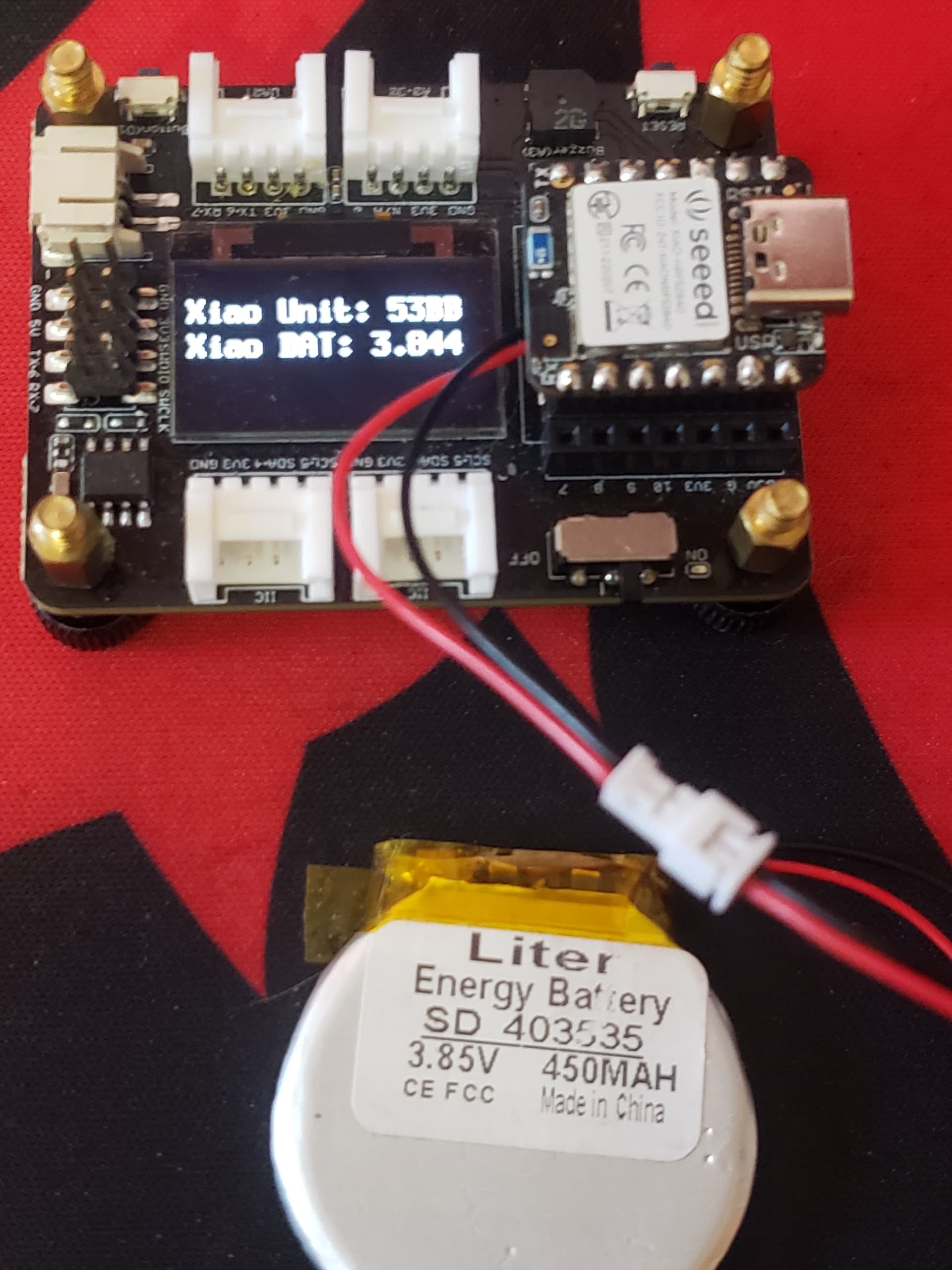
// XIAO VBAT Measurement
//
// Set the GPIO PIN and ADC configuration for VBat measurements
void SetVBatMeasurement() {
pinMode(PIN_VBAT, INPUT); //Battery Voltage monitoring pin
pinMode(VBAT_ENABLE, OUTPUT); //Enable Battery Voltage monitoring pin
digitalWrite(VBAT_ENABLE, LOW); //Enable
analogReference(AR_INTERNAL_2_4); //Vref=2.4V
analogReadResolution(12); //12bits
}
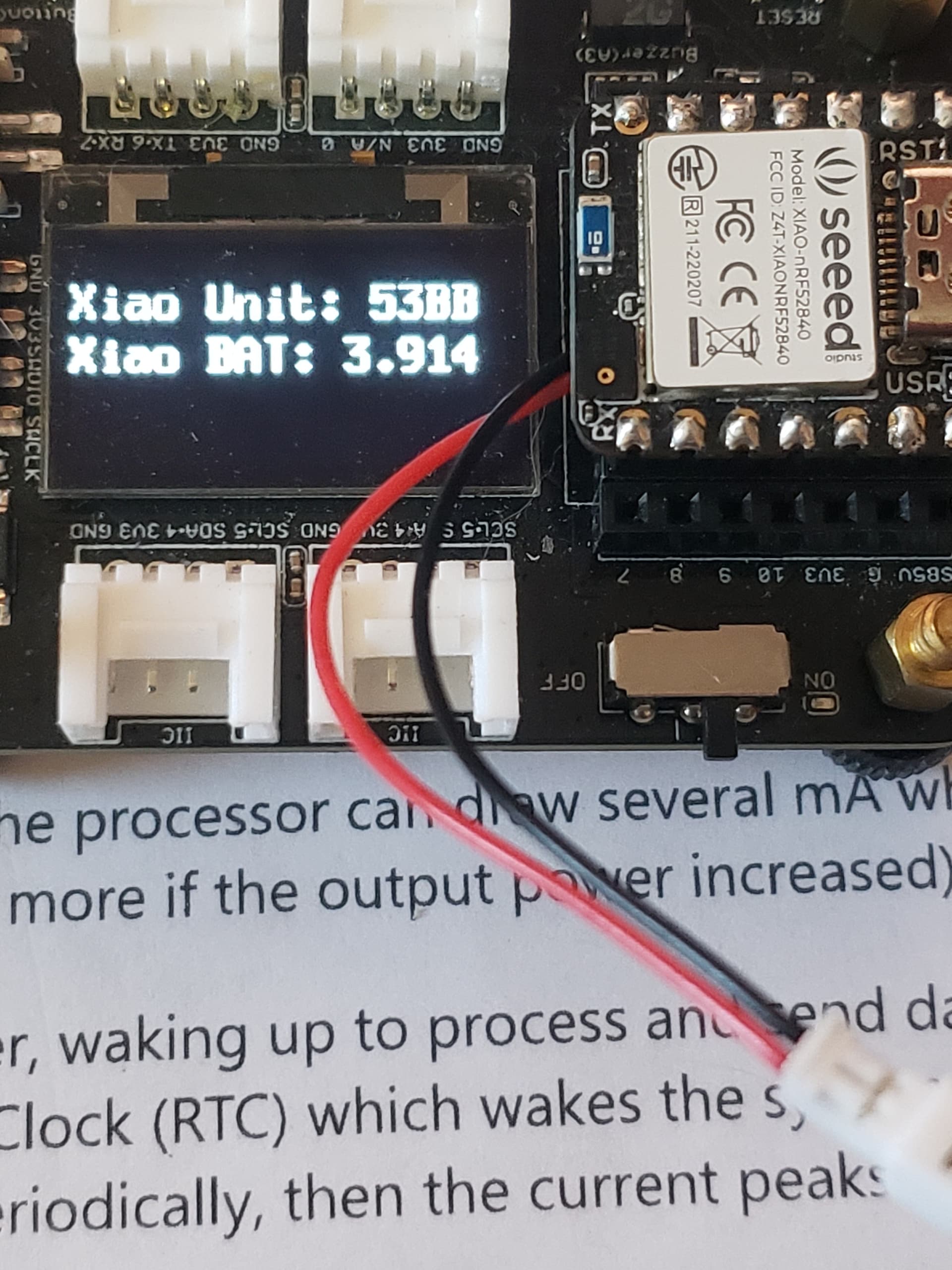
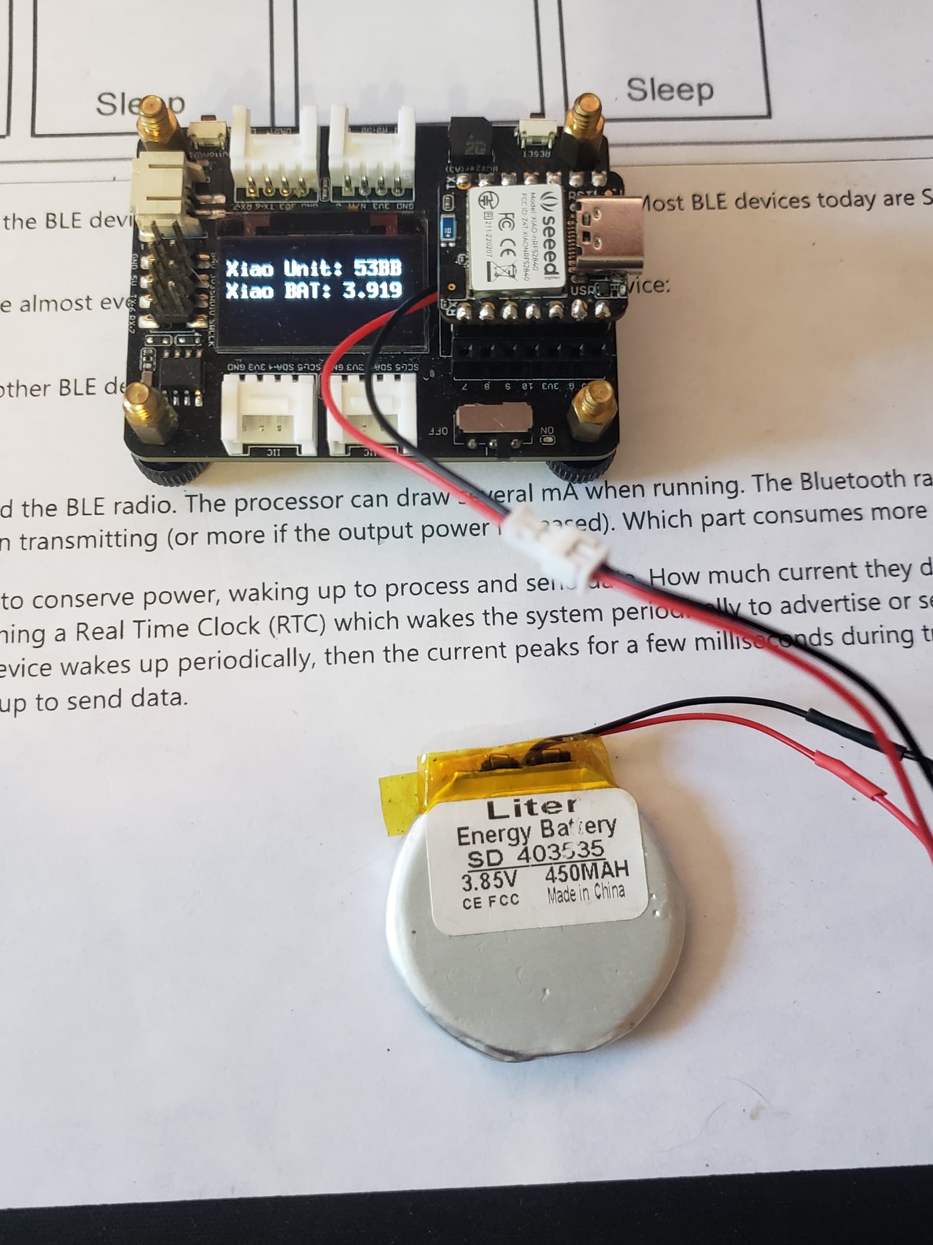
// Perform a VBat voltage Read
#define VBatAdj (3.970 / 3.892) // 2% Uncertainty: in specifications
float ReadVbat() {
// Read VBAT voltage
pinMode(VBAT_ENABLE, OUTPUT); //Enable Battery Voltage monitoring pin
digitalWrite(VBAT_ENABLE, LOW); //Enable
digitalWrite(LED_RED, LOW); // turn the LED on (HIGH is the voltage level)
delay(200); // To be sure the pin voltage is stable
int VBatMin = 4096;
int VBatMax = 0;
int VBat = 0;
for (int i = 0; i < 10; i++) {
int v = analogRead(PIN_VBAT);
VBatMin = min(VBatMin, v);
VBatMax = max(VBatMax, v);
VBat += v;
delay(50);
}
VBat -= VBatMin; // Remove min ADC value
VBat -= VBatMax; // Remove max ADC value
VBat /= 8;
pinMode(VBAT_ENABLE, INPUT); //Disable Battery Voltage monitoring pin
digitalWrite(LED_RED, HIGH); // turn the LED off by making the voltage LOW
float Vbattery = ((510e3 + 1000e3) / 510e3) * 2.4 * VBat / 4096;
return (Vbattery * VBatAdj);
}
// Convert VBat in %
int ConvertVBatInPercent(float v) {
long int iv = (long int)(v * 1000.0);
long int val = map(iv, 3100, 4100, 0, 100);
return ((int)val);
}

// the setup function runs once when you press reset or power the board
void setup() {

Serial.begin(115200);
// initialize digital pin LED_BUILTIN as an output.
pinMode(LED_BLUE, OUTPUT);
pinMode(LED_GREEN, OUTPUT);
pinMode(LED_RED, OUTPUT);
delay(5000);
Serial.println("---- TEST XIAO");
// TestString = “TEST String”;
#define HICHG (13)
// pinMode(HICHG, OUTPUT); //Charge Current setting pin
// digitalWrite(HICHG, HIGH); //Charge Current 0:100mA, 1:50mA
SetVBatMeasurement();

Serial.println("- RUN LED -");
digitalWrite(LED_BLUE, LOW); // turn the LED on (HIGH is the voltage level)
delay(1000); // wait for a second
digitalWrite(LED_BLUE, HIGH); // turn the LED off by making the voltage LOW
delay(1000); // wait for a second
digitalWrite(LED_GREEN, LOW); // turn the LED on (HIGH is the voltage level)
delay(1000); // wait for a second
digitalWrite(LED_GREEN, HIGH); // turn the LED off by making the voltage LOW
delay(1000); // wait for a second
digitalWrite(LED_RED, LOW); // turn the LED on (HIGH is the voltage level)
delay(1000); // wait for a second
digitalWrite(LED_RED, HIGH); // turn the LED off by making the voltage LOW
delay(1000); // wait for a second
}

// the loop function runs over and over again forever
void loop() {
float vb = ReadVbat();
Serial.print(vb * 100);
Serial.print(F(", "));
Serial.println(ConvertVBatInPercent(vb));
delay(700);
Serial.println(TestString);
}

Hello,
Is this thing ON? Why is it marked SOLVED? WTH? :grimacing:
I wonder if we will ever be able to read the battery voltage on the Xiao nRf52840 BLE Sense micro?. Why is this a problem? I’m using

Using library ArduinoBLE at version 1.3.4 in folder: D:\Arduino_projects\libraries\ArduinoBLE 
Using library Seeed Arduino LSM6DS3 at version 2.0.3 in folder: D:\Arduino_projects\libraries\Seeed_Arduino_LSM6DS3 
Using library Wire in folder: C:\Users\Dude\AppData\Local\Arduino15\packages\Seeeduino\hardware\mbed\2.9.1\libraries\Wire (legacy)
Using library SPI in folder: C:\Users\Dude\AppData\Local\Arduino15\packages\Seeeduino\hardware\mbed\2.9.1\libraries\SPI (legacy)
--Removed for clarity--
Sketch uses 342496 bytes (42%) of program storage space. Maximum is 811008 bytes.
Global variables use 72160 bytes (30%) of dynamic memory, leaving 165408 bytes for local variables. Maximum is 237568 bytes.

Everything else works, C’mon Seeed what’s up with this stuff?
GL
:non-potable_water:

Hi Folks,

I was looking for a way to read the voltage of the battery on the xiao ble sense nrf52840 (that is actually connected to the Expansion board) but I ran into this post.

So if I understand correctly there was the issue that
analogRead(PIN_VBAT) hangs the IDE ----> GREEN LED ON/OFF hangs the IDE

It has been fixed with a patch but now I read in that post
that the reading is not consistent and also
and when you put the device in deep sleep and wake it up, you get no reading at all?

Could somebody give an update about what works and what doesn’t ?

Also does this issue happen only when you read VBAT pin from the xiao ble sense nrf52840
and the battery’s wires are soldered to Bat+ and Bat- pads ?

Or could the issue happen too if the battery is plugged to the JST connector on the Expansion board and you read the battery pin ? Which I don’t even know if it’s possible on the Expansion board because I don’t know if the BATT pin can be read by the MCU.

That’s the Expansion board schematic:
Expansion board schematic

Would appreciate any insightful input on this.

Thanks.
Cheers !

Hi there and welcome to the SHOW… :grinning:

Ah’s the SEEED Studio’s
The code name “XIAO” here represents its half feature “Tiny”, and the other half will be “Puissant”. :grinning:

"Elaborate Power Design: Provide ultra-low power consumption as 5 μA in deep sleep mode while supporting lithium battery charge management"

"Seeed Studio XIAO nRF52840 Sense is carrying Bluetooth 5.0 wireless capability and is able to operate with low power consumption."

"strong software compatibilities, which supports Arduino, Micropython, and CircuitPython. Except for the software"

YMMV...

IMHO, They need a DISCLAIMER though! (none of the battery crap works out of the box)
:stuck_out_tongue_closed_eyes:
I suggest you look at this post HERE, Msfujino He has the battery reading on the Expansion board mod on Lock. :wink: :+1:

SEEED engineering a.k.a. (marketing) on the other hand DOES NOT!!! :v:

HTH
GL :-p

1 Like

Hi lguapo,

The battery connected to the JST connector on the XIAO_Expansion_Board is not connected to the XIAO port, so the voltage cannot be read. The modification in the link below #1 allows you to read the battery voltage with analonRead(A0).
XIAO nRF52840(mbed) 1-Central 2-Peripherals Project "Sleeping Posture, Heart rate, Pulse oximetry Monitor"

The battery voltage connected to the pad on the back side of XIAO can be read with analogRead(P0_31) or analogRead(PIN_VBAT). However, when using Board Service Package:“Seeed nRF52 mbed-enable Borads 2.9.1”, the patch in this post #31 is required; when using “Seeed nRF52 Boards 1.1.1”, no patch is required.

1 Like

Yes, XIAO for tiny but can be a big pain in the a** too sometimes.
I wish their doc and wiki was a bit better.
As you mentioned before, Adafruit’s doc is walk in the park on a sunny Sunday with an ice-cream in your hand compared to Seeed.

Maybe it’ll get better over time.

1 Like