XIAO BLE Sense - LSM6DS3 INT1 Single Tap Interrupt

Just add
delay(100);
after
nrf_gpio_cfg_sense_input(digitalPinToInterrupt(int1Pin), NRF_GPIO_PIN_PULLDOWN, NRF_GPIO_PIN_SENSE_HIGH);
then the code will work for battery.

1 Like

This method worked for me thank you :slight_smile:

Hey @chuck when you were in sleep mode. Was there a way for you to save data during sleep mode. E.g storing imu data.

Hi @jonyu,
currently i didn’t need to save IMU data while sleeping. But you should be able to save your measurements (up 4kB i think) in integrated FIFO of LSM6DS3, and read everything at once after wake up.

@chuck thank you for the example code!!

did you manage to get any further optimisations in terms of power draw? would turning the mic off help? A couple of things I’m trying to get my head round:

  • what is the difference between sd_power_system_off(); and NRF_POWER->SYSTEMOFF = 1;
  • would sd_power_mode_set(NRF_POWER_MODE_LOWPWR);, sd_power_dcdc_mode_set(NRF_POWER_DCDC_ENABLE);, __WFE();, __WFI();, sd_app_evt_wait(); help at all?

I’m trying to get a battery powered wearable working which is effectively completely powered down (no mic, BLE, data persistence etc so system resets are fine) when not in use, but can be woken up/powered down with a double tap.

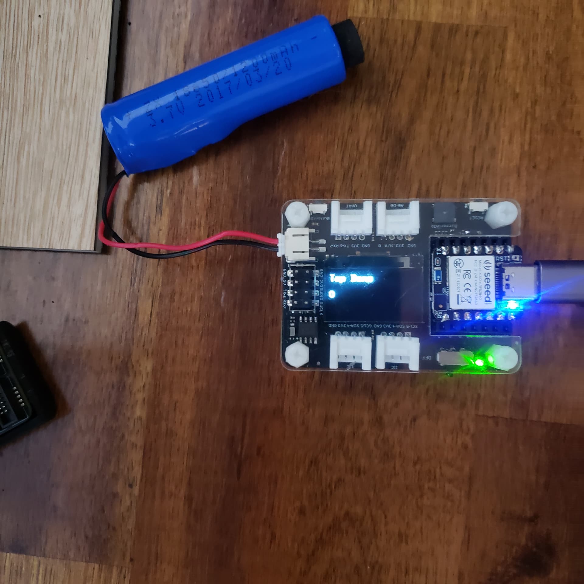
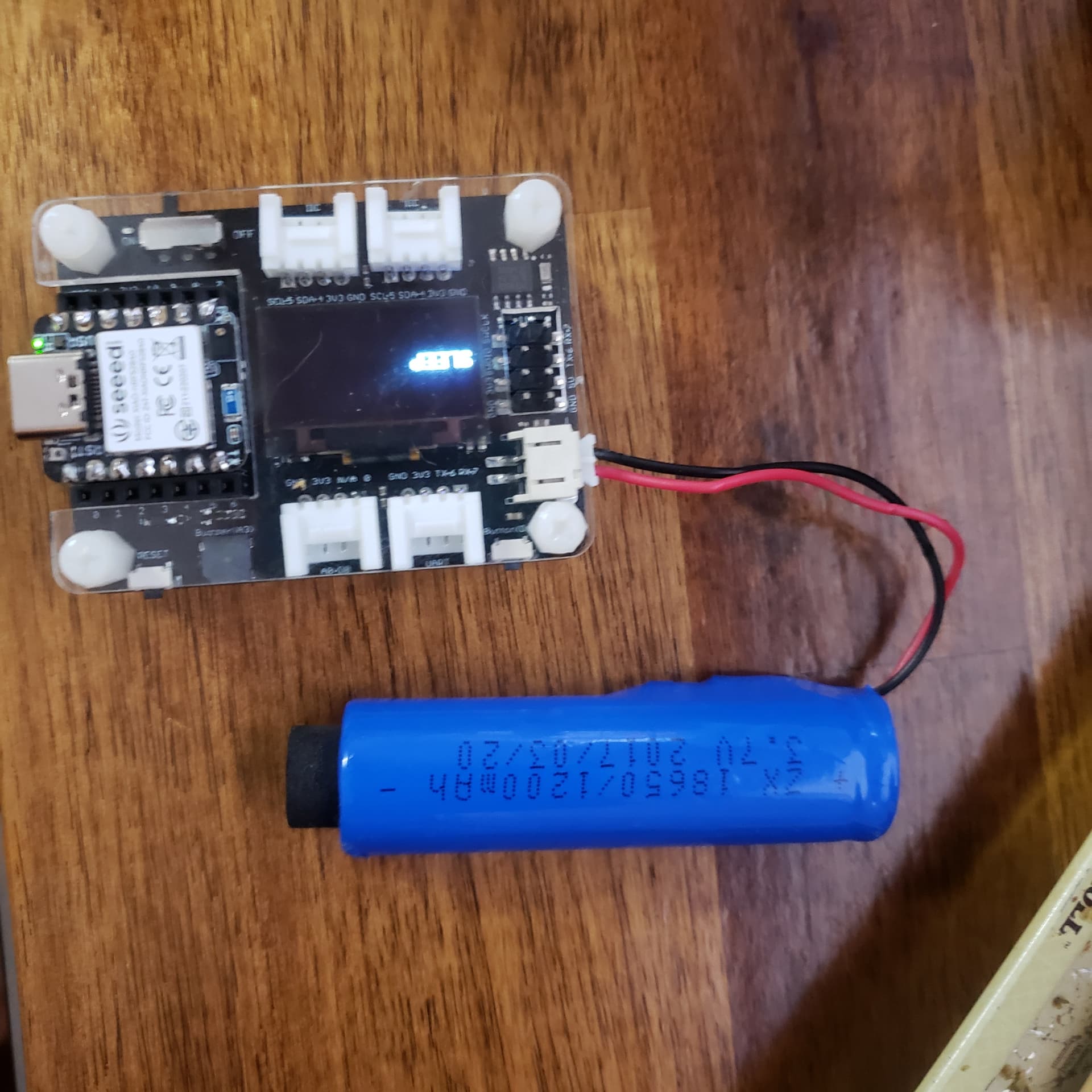
XIAO BLE Sense - LSM6DS3 INT1 Double Tap Interrupt Xiao Expansion Board OLED TAP DEMO
/*****************************************************************************/

// IMU Interrupt Example for XIAO BLE Sense

// This example shows how to configure LMSD6S3TR-C on XIAO BLE SENSE to interrupt

// on INT1 after a “Double Tap” was recognized.

// Additionally, the device goes into System OFF state, after 5 interrupts were

// received. Another “Double Tap” will wake up the device again.

//

// Original by chuck

Go See it running HERE------>>>Expansion Board TAP DEMO video


HTG
GL :slight_smile:

/*****************************************************************************/
// IMU Interrupt Example for XIAO BLE Sense
// This example shows how to configure LMSD6S3TR-C on XIAO BLE SENSE to interrupt
// on INT1 after a "Double Tap" was recognized.
// Additionally, the device goes into System OFF state, after 5 interrupts were
// received. Another "Double Tap" will wake up the device again.
// 
// Original by chuck
//poatched and toasted by pjg
/*******************************************************************************/

#include "LSM6DS3.h"
#include "Wire.h"
#include <U8x8lib.h>
LSM6DS3 myIMU(I2C_MODE, 0x6A); // IMU 
#define int1Pin PIN_LSM6DS3TR_C_INT1

U8X8_SSD1306_128X64_NONAME_HW_I2C u8x8(/* clock=*/ PIN_WIRE_SCL, /* data=*/ PIN_WIRE_SDA, /* reset=*/ U8X8_PIN_NONE);
 // OLEDs without Reset of the Display

const int buttonPin = 1;     // the number of the pushbutton pin
int buttonState = 0;         // variable for reading the pushbutton status
int BuzzerPin = A3;
uint8_t interruptCount = 0; // Amount of received interrupts
uint8_t prevInterruptCount = 0; // Interrupt Counter from last loop


void setup() {
    Serial.begin(9600);
	  delay(1000); //relax...
	  Serial.println("Processor came out of reset.\n");
    u8x8.begin();
    u8x8.setFlipMode(1);   // set number from 1 to 3, the screen word will rotary 180
    
    pinMode(LED_BUILTIN, OUTPUT);// initialize the LED pin as an output:
    pinMode(buttonPin, INPUT_PULLUP);// initialize the pushbutton pin as an input:
    pinMode(BuzzerPin, OUTPUT);
    pinMode(LEDR, OUTPUT);
    pinMode(LEDG, OUTPUT);
    pinMode(LEDB, OUTPUT);
    setLedRGB(false, false, true); // set blue led

    myIMU.settings.gyroEnabled = 0; // Gyro currently not used, disabled to save power 
    if (myIMU.begin() != 0) {
        Serial.println("IMU error");
    } else {
        Serial.println("IMU OK!");
    }
    
    setupDoubleTapInterrupt();
    
    pinMode(int1Pin, INPUT);
    attachInterrupt(digitalPinToInterrupt(int1Pin), int1ISR, RISING);
    u8x8.setFont(u8x8_font_8x13B_1x2_r);
    u8x8.clearDisplay();
    u8x8.setCursor(0, 0);
    u8x8.print("Tap Demo");
  
}

void loop() {
    setLedRGB(false, false, true); // reset led to blue only
    u8x8.setCursor(0, 3);
    u8x8.print(interruptCount);
    Serial.print("\Iterrupt Counter: ");
    Serial.println(interruptCount);

    // if interrupt was received in this cycle
    if (interruptCount > prevInterruptCount) {
      Serial.println("\Interrupt received!");
      setLedRGB(false, true, false); // set green only
    }
    
    prevInterruptCount = interruptCount;
    
    if (interruptCount >= 5) {
      // Trigger System OFF after 5 interrupts
      goToPowerOff();
    }
    
    delay(500);
}


// -------------------- System ------------------------- //

void goToPowerOff() {
  setLedRGB(false, false, false);
  Serial.println("Going to System OFF");
  u8x8.clearDisplay();
  u8x8.setCursor(0, 3);
  u8x8.print("SLEEP");
  setupDoubleTapInterrupt(); // not needed here, if already applied..
  delay(1000); // delay seems important to apply settings, before going to System OFF
  //Ensure interrupt pin from IMU is set to wake up device
  nrf_gpio_cfg_sense_input(digitalPinToInterrupt(int1Pin), NRF_GPIO_PIN_PULLDOWN, NRF_GPIO_PIN_SENSE_HIGH);
  // Trigger System OFF
  NRF_POWER->SYSTEMOFF = 1;
}

// -------------------- Interrupts ------------------------- //

void setupDoubleTapInterrupt() {
  uint8_t error = 0;
  uint8_t dataToWrite = 0;

  // Double Tap Config
  myIMU.writeRegister(LSM6DS3_ACC_GYRO_CTRL1_XL, 0x60); //* Acc = 416Hz (High-Performance mode)// Turn on the accelerometer
  // ODR_XL = 416 Hz, FS_XL = 2g
  myIMU.writeRegister(LSM6DS3_ACC_GYRO_TAP_CFG1, 0x8E);// INTERRUPTS_ENABLE, SLOPE_FDS// Enable interrupts and tap detection on X, Y, Z-axis
  myIMU.writeRegister(LSM6DS3_ACC_GYRO_TAP_THS_6D, 0x85);// Set tap threshold 8C
  myIMU.writeRegister(LSM6DS3_ACC_GYRO_INT_DUR2, 0x7F);// Set Duration, Quiet and Shock time windows 7F
  myIMU.writeRegister(LSM6DS3_ACC_GYRO_WAKE_UP_THS, 0x80);// Single & double-tap enabled (SINGLE_DOUBLE_TAP = 1)
  myIMU.writeRegister(LSM6DS3_ACC_GYRO_MD1_CFG, 0x08);// Double-tap interrupt driven to INT1 pin
}

void int1ISR()
{
  interruptCount++;
 ;
  
}

// -------------------- Utilities ------------------------- //

void setLedRGB(bool red, bool green, bool blue) {
  if (!blue) { digitalWrite(LEDB, HIGH); } else { digitalWrite(LEDB, LOW); }
  if (!green) { digitalWrite(LEDG, HIGH); } else { digitalWrite(LEDG, LOW); }
  if (!red) { digitalWrite(LEDR, HIGH); } else { digitalWrite(LEDR, LOW); }
}
3 Likes

@PJ_Glasso Thank you for sharing this code. It works fine with a battery after added 100ms delay as qqice mentioned. But in the sleep mode, why the battery charging indicator LED is ON?
Thanks.

Hello everyone. I wondered that is there a way to put XIAO BLE Sense into deep sleep mode with mbed-enabled library? I failed to archive uA level current.

Hi there, Well I haven’t had time yet to measure the consumption from aforeposted code, but I’m using the mbed 2.9.0 and it works AOK.
3 key sections which are imo the “crux of the biscuit” :slight_smile: to it…
1- config interrupt pin & Do some lower power IMU mode

LSM6DS3 myIMU(I2C_MODE, 0x6A); // IMU 
#define int1Pin PIN_LSM6DS3TR_C_INT1
--
myIMU.settings.gyroEnabled = 0; *// Gyro currently not used, disabled to save power* 

interrupts & pins

setupDoubleTapInterrupt();
    
    pinMode(int1Pin, INPUT);
    attachInterrupt(digitalPinToInterrupt(int1Pin), int1ISR, RISING);

3- config correct sleep mode interrupt & pin

//Ensure interrupt pin from IMU is set to wake up device
  nrf_gpio_cfg_sense_input(digitalPinToInterrupt(int1Pin), NRF_GPIO_PIN_PULLDOWN, NRF_GPIO_PIN_SENSE_HIGH);
  // Trigger System OFF
  NRF_POWER->SYSTEMOFF = 1;
}

Those are my tips and key as to how it works.
HTH
GL :-p

What is your current draw?

How low did you go with current consumption in sleep? I managed 100uA but that is too high for me.

Lowest on the PPK2 recording was1.24 ma. in sleep? :face_with_symbols_over_mouth:
as is with code from above and the 2ms delay in shutdown.


Needs more adjustment for Low Power this was just a double tap demo, FYI…
HTH
GL:-)
DUT, configuration…pic

Do you know if the LM6DS3TR_C_INT2 pin is connected anywhere? It’s not defined in Seeed Xiao non-Mbed 1.0.0 firmware. It seems to be needed for the “Absolute Wrist Tilt” embedded low power feature to generate an interrupt.

I believe tilt detection and Absolute Wrist Tilt are the two low-power interrupt functions that can use the low-power ODRs of the accelerometer, while others like double tap might use up more power. The accelerometer in high performance mode uses 160 μA, while the low-power mode uses 9 μA.

A_IddHP
Accelerometer current
consumption
in high-performance mode
ODR < 1.6 kHz
ODR ≥ 1.6 kHz
150
160 μA
LA_IddNM Accelerometer current
consumption in normal mode ODR = 208 Hz 85 μA
LA_IddLM Accelerometer current
consumption in low-power mode ODR = 12.5 Hz 9 μA

iNEMO inertial module: always-on 3D accelerometer and 3D gyroscope (st.com)

@PJ_Glasso
Do you notice that whenever you measure with PPK2, there is always a ripple superimposed on the current waveform? Could you measure with a resistor and see if it still exists?
ppk2

It’s a issue with the over sampling with the PPK2 I always use the extra GND from the logic port to the GND of the chip(xiao), FWIW. Nordic forums has some topics about the PPK2, just lower the number of samples and go again.

Were you able to use a TILT interupt , if so how, did you write the registers directly? I guess too many Libs for the IMU, last count there’s at least 3. ?
Fun stuff… :smile:
HTH

GL :slight_smile:

From Seeed’s own SOM schematic link. Looks like they took the easiest way out. Must have been billed by the trace :laughing:
No sound engineering reason except it wouldn’t pass FCC or some such?
ONE INT is ALL you GET :face_with_open_eyes_and_hand_over_mouth:


HTH
GL:-)

I guess the absolute wrist tilt function won’t work then!

I wrote the registers using lines like myIMU.writeRegister(LSM6DS3_ACC_GYRO_CTRL10_C, B10001100); //enable wrist tilt algorithm, following the datasheet .

I replaced the IMU interrupt with a SignalQuest SQ-SEN-815B tilt sensor that is zero power when not activated and 50uA when activated. It can be soldered directly to two pins spaced 3 holes apart on the Xiao, one of which is ground, and wakes with your interrupt sense pin pulldown code.

Even with this the Xiao BLE Sense still seems to kill the 95mAh battery in a day while in deep sleep, so I ordered a Nordic PPK2 to check why. It might be because of a Neopixel that I am sinking through the device. I wonder if the IMU and microphone take up a lot of power when they aren’t even initiated in the code?

Hi there,
Yes the PPK2 is worth the hondo for sure, hepled me shave allot of power wasting in y code, I’m goona have a look at the IMU data sheett and see what else is possible. Amazingly short sighted on Seeed Engineering’s part to leave such capabilities on the floor.
HTH
GL :slight_smile:

What’s Your opinion ?

  • can I replace PPK2 with oscilloscope + small resistor ? how small ?
    Thanks for advice.
    PPK2 is pretty expensive :frowning:

Hi AdamM68,
Information about ppk2 can be found here. Schematics and manuals are included.
I got it and it is a very well designed and reliable unit.

Power Profiler Kit II - Downloads - nordicsemi.com