Hi,
As XIAO has on chip battery charging module, is it possible get battery level reading and charging status? I am going to build a mobile app which will connect to XIAO over bluetooth and I want show the battery level on the app and also charging status when it’s charging.
The design of the charging module takes into account that users may turn the xiao ble into a smart wearable device that requires lithium battery power supply. As for the detection of battery voltage, the ADC function is involved, and secondary development requires your efforts.
Thanks. I am powering XIAO by 3.7v LiPo battery. Wondering if reading analog value from A0 would be a good idea. Any guidance would be helpful.
The A0 pin is an analog pin, it should be fine
But don’t forget a voltage divider. 3.7V is too much for A0.

Thanks. I guess I need a little more help. I set P0_14 to OUTPUT and trying to read P0_31 but getting value of -1 always.
code snippet
void setup(){
pinMode(P0_14, OUTPUT);
pinMode(P0_31, INPUT);
}

void loop(){
   float batV = analogRead(P0_31);  //this reads to -1
}I tried to fix the code.
I haven’t used XIAO BLE yet, so I’m not sure if the code below works.
void setup(){
pinMode(P0_14, OUTPUT);
digitalWrite(P0_14,LOW);
// pinMode(P0_31, INPUT);
}
void loop(){
unsigned int TempV = analogRead(P0_31); // Read AD to unsigned integer
float BatV = TempV * 510 / 1510 * ADresolution; // “Adresolution” must be define
}
Tried Match-san’s code on XIAO BLE Sense.
I have the same result as mithundotdas.
Any clues ?
@Kactum I am not successful yet either. I am getting a constant reading of 4294 ( with ADresolution set to 1 for example ). This values is not changing when battery is draining. What’s your observation ?
I tried the code below :
#include <Arduino.h>

uint8_t ADresolution = 1;

void setup()
{
  Serial.begin(9600);
  pinMode(P0_14, OUTPUT);
  digitalWrite(P0_14, LOW);
  // pinMode(P0_31, INPUT);

}

void loop()
{
  unsigned int TempV = analogRead(P0_31);         // Read AD to unsigned integer
  float BatV = TempV * 510 / 1510 * ADresolution; // “Adresolution” must be define
  Serial.print(TempV);
  Serial.print(" ");
  Serial.println(BatV);
  delay(200);
}
It gives me :
4294967295 for TempV
2844348.00 dor BatV
I have no changes in the value even if i unplugged the li-po.
Maybe we need to activate something for the ADC ?
Right. No change in value. I am wondering if P0_31 reading is meant for this. Other option could be to use A0 pin as INPUT and connect Lipo positive to A0 ( using voltage divider) .
I just received my XIAO BLE Sense board and was disappointed to see this thread indicating problems reading the battery voltage.
I note that the return value trying analogRead from P0_31 is 0xFFFFFFFF, which is the traditional return value when trying to do an analogRead from a pin not connected to an ADC input.
So, poking around in the pins_arduino.h file in the variants directory for this board, I found the following:
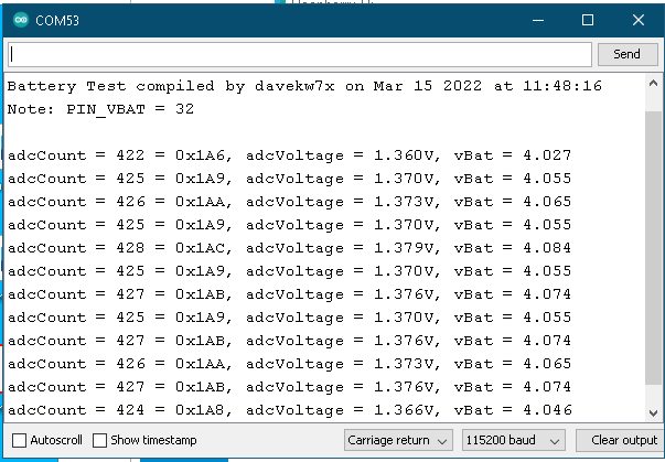
#define PIN_VBAT (32u)I decided to try PIN_VBAT in my analogRead, and, guess what?
Taa-daa!
Here’s my test sketch:
/*
 * Test to read a LiPo battery connected to VBAT on the
 * underside of XIAO BLE boards.
 *
 * Note that the ADC input from the VBAT voltage divider is
 * NOT pin P0_31 as shown on the schematic!
 *
 * March, 2022
 * davekw7x
 */
// For mbed compilers, the following allows us to use the
// standard printf() function.
REDIRECT_STDOUT_TO(Serial)

void setup()
{
  pinMode(LED_BUILTIN, OUTPUT);
  Serial.begin(115200);
  while (!Serial)
    ;
  printf("\nBattery Test compiled by davekw7x on %s at %s\n",   __DATE__, __TIME__);
  printf("Note: PIN_VBAT = %u\n\n", PIN_VBAT);

  pinMode(P0_14, OUTPUT);
  digitalWrite(P0_14, LOW);
}  // End of setup()

const double vRef = 3.3; // Assumes 3.3V regulator output is ADC reference voltage
const unsigned int numReadings = 1024; // 10-bit ADC readings 0-1023, so the factor is 1024

void loop()
{
  unsigned int adcCount = analogRead(PIN_VBAT);
  double adcVoltage = (adcCount * vRef) / numReadings;
  double vBat = adcVoltage*1510.0/510.0; // Voltage divider from Vbat to ADC

  printf("adcCount = %3u = 0x%03X, adcVoltage = %.3fV, vBat = %.3f\n",
             adcCount, adcCount, adcVoltage, vBat);

  digitalWrite(LED_BUILTIN, !digitalRead(LED_BUILTIN));
  delay(1000);
} // End of loop()
And here’s the output, consistent with my very freshly charged LiPo battery:
Regards,
Dave
Thanks Dave ! Unfortunately the code is not working for me. I am using BLE and IMU and the moment I am reading from PIN_VBAT, peripheral gets disconnected. Not sure if I am missing any bit.
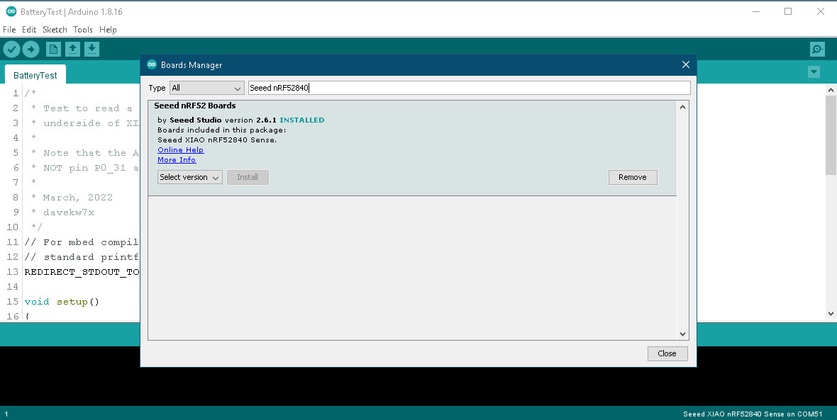
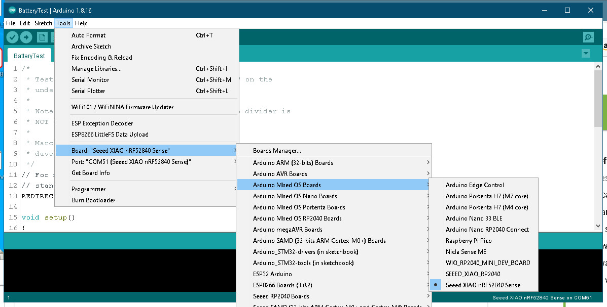
I posted the exact sketch I used to get the indicated output
Here is the setup information for my Sketch on Windows 10 using Arduino 1.8.16
I tacked small wires (30 gauge stranded) to the BAT and GND pads on the underside of the XIAO BLE Sense board and connected to a battery holder for my LiPo.
Of course I ran the sketch with no battery installed first, and saw “drifting” values for the ADC reading—all of them within the 10-bit range of the ADC. Then I installed the battery and got the measurements I showed.
Regards,
Dave
Thanks Dave
I got XIAO BLE.
I’ll try your codes.
Match
Hi Dave! I tested your code and I was able to get the reading. But problem is when using the same code with BLE & IMU together. In my code, I am sending IMU data over bluetooth to a mobile app and reading PIN_VBAT disconnects the device from mobile app. An example code would be like this
/**
This prorgam is written to collect IMU data from XIAO BLE Sense and send to EI Blue mobile app.
EI Blue mobile app uploads the data to Edge Impulse Studio.
Visit https://wiki.seeedstudio.com/XIAO-BLE-Sense-Bluetooth-Usage/ to setup Arduino IDE
Get EI Blue mobile app from https://github.com/just4give/ei-blue
*/
#include <ArduinoBLE.h>
#include <LSM6DS3.h>
#include <Wire.h>

#define BLENAME                       "EIBLUE"
#define SERVICE_UUID                  "4D7D1101-EE27-40B2-836C-17505C1044D7"
#define TX_PRED_CHAR_UUID             "4D7D1106-EE27-40B2-836C-17505C1044D7"
#define TX_BAT_CHAR_UUID              "4D7D1107-EE27-40B2-836C-17505C1044D7"
#define RX_CHAR_UUID                  "4D7D1108-EE27-40B2-836C-17505C1044D7"
#define SAMPLING_RATE                 50   //Hz
#define DURATION                      1 //seconds


BLEService bleService(SERVICE_UUID); // Bluetooth® Low Energy LED Service

// Bluetooth® Low Energy LED Switch Characteristic - custom 128-bit UUID, read and writable by central
BLEStringCharacteristic rxCharacteristic(RX_CHAR_UUID, BLEWrite, 1024);
BLEStringCharacteristic txPredCharacteristic(TX_PRED_CHAR_UUID, BLERead | BLENotify, 1024);
BLEStringCharacteristic txBatCharacteristic(TX_BAT_CHAR_UUID, BLERead | BLENotify, 1024);

LSM6DS3 myIMU(I2C_MODE, 0x6A);    //I2C device address 0x6A
float aX, aY, aZ, gX, gY, gZ;
const float accelerationThreshold = 2.5; // threshold of significant in G's


const double vRef = 3.3; // Assumes 3.3V regulator output is ADC reference voltage
const unsigned int numReadings = 1024;

void setup() {
  Serial.begin(115200);

  pinMode(P0_14, OUTPUT);
  digitalWrite(P0_14,LOW);

  // set LED pin to output mode
  pinMode(LEDB, OUTPUT);
  pinMode(LEDR, OUTPUT);
  pinMode(LEDG, OUTPUT);

  digitalWrite(LEDR, HIGH);
  digitalWrite(LEDB, HIGH);
  digitalWrite(LEDG, LOW);


  // begin initialization
  if (!BLE.begin()) {
    Serial.println("starting Bluetooth® Low Energy module failed!");

    while (1);
  }

  // set advertised local name and service UUID:
  BLE.setLocalName(BLENAME);
  BLE.setDeviceName(BLENAME);
  BLE.setAdvertisedService(bleService);

  // add the characteristic to the service
  bleService.addCharacteristic(txBatCharacteristic);
  bleService.addCharacteristic(txPredCharacteristic);
  bleService.addCharacteristic(rxCharacteristic);

  // add service
  BLE.addService(bleService);

  BLE.setEventHandler(BLEConnected, blePeripheralConnectHandler);
  BLE.setEventHandler(BLEDisconnected, blePeripheralDisconnectHandler);


  // start advertising
  BLE.advertise();

  Serial.println("BLE Peripheral");

  if (myIMU.begin() != 0) {
    Serial.println("Device error");
  } else {
    Serial.println("aX,aY,aZ,gX,gY,gZ");
  }

}

void loop() {

  BLEDevice central = BLE.central();

  if (central) {
  Serial.print("Connected to central: ");
  unsigned int adcCount = analogRead(PIN_VBAT);
  double adcVoltage = (adcCount * vRef) / numReadings;
  double vBat = adcVoltage*1510.0/510.0; // Voltage divider from Vbat to ADC

  printf("adcCount = %3u = 0x%03X, adcVoltage = %.3fV, vBat = %.3f\n",
             adcCount, adcCount, adcVoltage, vBat);


    String data="";
    data =  String(myIMU.readFloatAccelX(), 3)+","+String(myIMU.readFloatAccelY(), 3)+","+String(myIMU.readFloatAccelZ(), 3);


    txBatCharacteristic.writeValue(String(vBat));
    txPredCharacteristic.writeValue(data.c_str());

    delay(1000);
  }
}

void blePeripheralConnectHandler(BLEDevice central) {
  // central connected event handler
  Serial.print("Connected event, central: ");
  Serial.println(central.address());
  digitalWrite(LEDB, LOW);
  digitalWrite(LEDG, HIGH);
  digitalWrite(LEDR, HIGH);

}

void blePeripheralDisconnectHandler(BLEDevice central) {
  // central disconnected event handler
  Serial.print("Disconnected event, central: ");
  Serial.println(central.address());
  digitalWrite(LEDB, HIGH);
  digitalWrite(LEDG, LOW);
  digitalWrite(LEDR, HIGH);
}
I haven’t tried to access the LSM6DS3, but here’s the deal:
There are discrepancies between schematic and software that I haven’t figured out yet.
I’m leaving this project for the time being (got other fish to fry). Maybe, just maybe someone can get help from the folks at Seeed. Like, perhaps a real schematic and software examples that really work.
Here are some issues (Pardon my verbosity, but I just can’t seem to boil it down)
Issue 1:
The schematic shows pin 31 (P0.31) as the input to the ADC to read battery voltage through its voltage divider. We have all discovered that this does not work.
On the other hand, as I discovered, the arduino_pins.h header in the variants directory for this board defined PIN_VBAT to be 32.
That’s P1.0, but the schematic labels P1.0 as P1.00_PDM_CLK. I haven’t tried any PDM functions.
Bottom line: P1.0 works to read the ADC
Score so far: Software wins. (At least as far as reading the Battery Voltage.)
Issue 2:
Everyone on this thread, (including me) has used pin 14 (P0.14) as the active-low signal to ground one end of the voltage divider so that the battery voltage is scaled properly. This is shown on the schematic as P0_14_READ_BAT (with a bar over the ‘READ_BAT’ to indicate active-low).
However, in the arduino_pins.h, there is the following:
#define PIN_LSM6DS3TR_C_POWER (14u)The Seeed_Arduino_LSM6DS3 library that you are apparently using causes PIN_LSM6DS3TR_C_POWER to go high once (during the begin() method) to access the LSM6DS3. I don’t know if that is the actual connection. In this case, the schematic shows the power pins and Chip Select pin for the LSM6DS3 are connected to a signal named 6D_PWR, which goes to P1.08 on the CPU, which is numerically pin 40.
Bottom line: If you can get the LSM6DS3 to work by making pin 14 High and you can read the battery by making pin 14 go low, then you have to set pin 14 high (every time) after reading the battery before accessing the LSM6D3. This might pinpoint the problem, but doesn’t sound practical in an application.
The problem is, of course, those connections are hidden below the shield, and I’m not going to pry things apart to see what really goes where, and I don’t have time for more software exploration.
Sorry, but I’m done for now—maybe done with Seeed forever. Got other (non-Seeed) things to do that actually pay the bills.
Regards,
Dave
I found a symbol about VBATT in valiant…cpp file.
// VBAT
{ P0_14, NULL, NULL, NULL }, // D31/VBAT_ENABLE
{ P0_31, NULL, NULL, NULL }, // D32/VBAT_READ
So, We can use VBAT_ENABLE with this statement.
#define PIN_VBATENABLE (31u) // this is not defined in pins_arduino.h file.
pinMode(PIN_VBATENABLE, OUTPUT);
digitalWrite(PIN_VBATENABLE, LOW);
I really appreciate your insight on this topic. I have some areas to explore as you indicated. Will post here if I am successful. Thanks again ![]()