I am using two boards, one that only sends UART messages via UART2 and one that receives them, and then re-sends them through UART1 to my PC to verify that the whole thing is working.
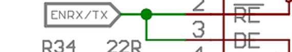
According to the board schematic, the RS485 port is controlled by the IC shown in the image below.
So, the first thing I tried was to check that the RS485 enable jumper (J17 in the image) was connected, which it was out of the box. Then, I set the ENRS485 pin (PB4) as a GPIO output, which I set high before calling HAL_UART_Transmit on UART2 and then back to low. On the receiving board, this pin is always low.
This didn’t work, so I looked into the HAL_UARTEx.c file (found within Drivers > STM32WLxx_HAL_Driver > Src) inside my STM32CubeIDE project. In there i found this function:
HAL_StatusTypeDef HAL_RS485Ex_Init(UART_HandleTypeDef *huart, uint32_t Polarity, uint32_t AssertionTime, uint32_t DeassertionTime);
I assumed that I had to use this instead of the HAL_UART_Init function that was automatically generated by the IDE:
static void MX_USART2_UART_Init(void)
{
  huart2.Instance = USART2;
  huart2.Init.BaudRate = 9600;
  huart2.Init.WordLength = UART_WORDLENGTH_8B;
  huart2.Init.StopBits = UART_STOPBITS_1;
  huart2.Init.Parity = UART_PARITY_NONE;
  huart2.Init.Mode = UART_MODE_TX_RX;
  huart2.Init.HwFlowCtl = UART_HWCONTROL_NONE;
  huart2.Init.OverSampling = UART_OVERSAMPLING_16;
  huart2.Init.OneBitSampling = UART_ONE_BIT_SAMPLE_DISABLE;
  huart2.Init.ClockPrescaler = UART_PRESCALER_DIV1;
  huart2.AdvancedInit.AdvFeatureInit = UART_ADVFEATURE_NO_INIT;
  if (HAL_UART_Init(&huart2) != HAL_OK)
  {
    Error_Handler();
  }
  if (HAL_UARTEx_SetTxFifoThreshold(&huart2, UART_TXFIFO_THRESHOLD_1_8) != HAL_OK)
  {
    Error_Handler();
  }
  if (HAL_UARTEx_SetRxFifoThreshold(&huart2, UART_RXFIFO_THRESHOLD_1_8) != HAL_OK)
  {
    Error_Handler();
  }
  if (HAL_UARTEx_DisableFifoMode(&huart2) != HAL_OK)
  {
    Error_Handler();
  }
}
So, I slighty modified the above function to use the RS485 initializer:
static void MX_USART2_UART_RS485_Init(void)
{
  huart2.Instance = USART2;
  huart2.Init.BaudRate = 9600;
  huart2.Init.WordLength = UART_WORDLENGTH_8B;
  huart2.Init.StopBits = UART_STOPBITS_1;
  huart2.Init.Parity = UART_PARITY_NONE;
  huart2.Init.Mode = UART_MODE_TX_RX;
  huart2.Init.HwFlowCtl = UART_HWCONTROL_NONE;
  huart2.Init.OverSampling = UART_OVERSAMPLING_16;
  huart2.Init.OneBitSampling = UART_ONE_BIT_SAMPLE_DISABLE;
  huart2.Init.ClockPrescaler = UART_PRESCALER_DIV1;
  huart2.AdvancedInit.AdvFeatureInit = UART_ADVFEATURE_NO_INIT;
  if (HAL_RS485Ex_Init(&huart2, UART_DE_POLARITY_HIGH, 8, 8) != HAL_OK)
  {
    Error_Handler();
  }
  if (HAL_UARTEx_SetTxFifoThreshold(&huart2, UART_TXFIFO_THRESHOLD_1_8) != HAL_OK)
  {
    Error_Handler();
  }
  if (HAL_UARTEx_SetRxFifoThreshold(&huart2, UART_RXFIFO_THRESHOLD_1_8) != HAL_OK)
  {
    Error_Handler();
  }
  if (HAL_UARTEx_DisableFifoMode(&huart2) != HAL_OK)
  {
    Error_Handler();
  }
}
Notice that the only change is in line 14. I figured out the parameters from this application note.
Still, it doesn’t work, and I think it’s because this initializer was made by STM for one of their boards, not the one I’m using. The IDE probably doesn’t even know that my board has an RS485 port, since when I created the project I only specified the MCU, not the board model itself.
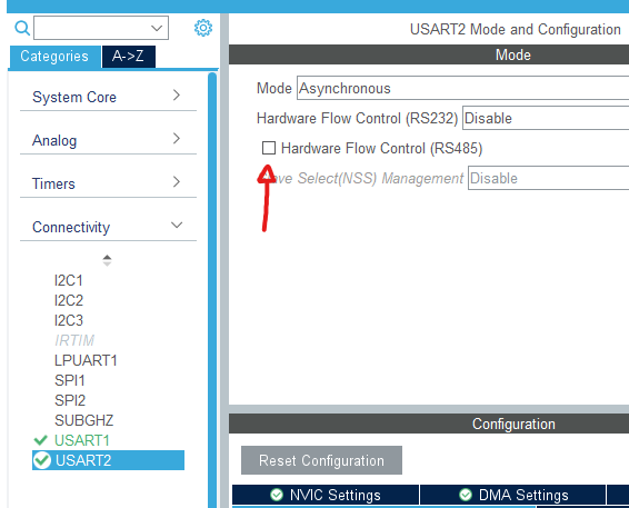
My third solution was to enable the Hardware Flow Control (RS485) option for UART2 in the project’s .ioc file, which in turn enabled the PA1 pin.
This didn’t solve anything, but it changed the default MX_USART2_UART_Init function to use HAL_RS485Ex_Init(&huart2, UART_DE_POLARITY_HIGH, 0, 0) as an initializer, like I did before but with slightly different parameters.
Then I tried to set the PA1 pin high before transmitting, then PB4 pin I’d tried before, and finally both pins. Nothing yet.