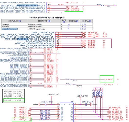
I found that GPIO1_16 (GPIO48) and GPIO2_0 (GPIO64) are connected in BeagleBone Green PCBs.
Does anyone know the reason why?
Also they are connected in BeagleBone Black, are NOT connected in BBB wireless nor BBG wireless.
Hi @kikuyuta
Please refer to below four parts of the screenshot.
(1) For GPIO2_0 (MMC2_CMD): there is a set of SDIO (MMC2) on the header, which can be connected to WiFi and the like. If you want to use it, you must have GPIO2_0 (MMC2_CMD). The WiFi on BBGW uses this group.
(2) For GPIO1_16 (GPIO48): there is a complete set of eHRPWM/eHRPWM1 on the header. If you use full functions, you must use GPIO1_16 (EHRPWM1_TRIPZONE_INPUT).
On BBGW, WiFi is already available, MMC2 is no longer needed, here GPIO2_0 is used, and then the two IOs are disassembled and not connected together.
This is why they are not connected in BBGW.
@jiachenglu
Thank you for your reply and giving me hints.
Unfortunately, I do not still understand why the two pins are connected in the original board.
I guess that developers can use some special function by the connection of the two pins, but I cannot find it. Otherwise, the guess might be wrong, so it probably be just saving header pins.
Hi @kikuyuta
There is no special purpose. The function of these two pins is to leave as many functions as possible and retain functions such as connecting to WiFi.
@jiachenglu, I understand very well. Thank you so much.
