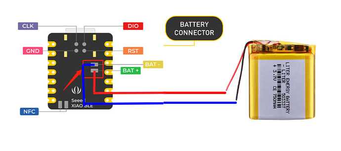
What is the consideration about battery charging exactly?

I have read this: What are the considerations when using XIAO nRF52840 (Sense) for battery charging? | Seeed Studio Wiki

When P0.14 (D14) turns off the ADC function at a high level of 3.3V, P0.31 will be at the input voltage limit of 3.6V. There is a risk of burning out the P0.31 pin.

Currently for this issue, we recommend that users do not turn off the ADC function of P0.14 (D14) or set P0.14 (D14) to high during battery charging.

First of all, how can P0.14 turn off the ADC function? Is there something specialty in P0.14 pin to control ADC function? As far as I know, I have to use some kind of resistor or API to disable ADC for usual MCUs.

Secondly, in (deep) sleep mode, the ADC will be turned off too. Does this mean that I cannot make XIAO nRF52840 BLE go into deep sleep mode? Or should I follow some special procedure to implement deep sleep?

Since I am going to use this board to implement DIY numpad, deep sleep mode is very important for me to save battery usage.
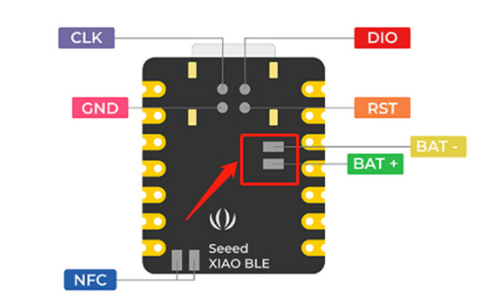
2 Likes

@Citric Please take a look,dear.

Thank you for answer.

I guess setting P0.14 to HIGH implicitly indicates setting pin mode of P0.14 to OUTPUT too.
This makes me think that, in other way, as far as I set the pin mode of P0.14 as INPUT, the ADC of P0.14 is always on and I can safely make XIAO go deep sleep. Am I correct?

Or, should I always set P0.14 to HIGH before sleep?

Is that because the ADC will be disabled anyway in sleep mode?

Do you mean it doesn’t matter to set HIGH or LOW before sleep?
Is it enough to set P0.14 to HIGH during charging only?

By the way, as soon as a user plugs USB, the charging will be started automatically.
How am I supposed to set P0.14 to HIGH before start charging?

Hello,

I apologize for the confusion caused earlier. After discussing with my colleagues, we realized that our previous explanation was not accurate. Allow me to clarify the situation, and I will delete the previous posts, keeping only the following message:

  1. The state of the P0.14 pin, whether it is pulled high or low, depends on whether you are charging the XIAO board using a battery. If you are powering it via USB, you won’t encounter any issues related to this.
  2. If you are charging the XIAO board using a battery, you need to pull the P0.14 pin low by connecting it to ground. This corrects the misinformation provided earlier.
  3. To enter sleep mode, it is also necessary to pull the P0.14 pin low. This means that during the charging process, you need to keep the ADC function enabled to avoid damaging the P0.31 pin.
1 Like

Thank you for answer.

I guess you mean powering XIAO board not charging here. Am I right?

I want to check I have correctly understood your explanations.

  1. P0.14 state doesn’t matter when powering XIAO board through USB → it is okay to set P0.14 low
  2. Set P0.14 to low when powering XIAO through a battery
  3. Set P0.14 to low to enter sleep mode with ADC function activated.

It seems awkward little bit because this means P0.14 just should be always low.
Is it still valid to set P0.14 to HIGH to prevent damaging P0.31 when ADC is turned off?
For instance, can I make XIAO enter sleep mode without ADC if I set P0.31 HIGH before entering sleep mode?

Does this include charging battery through USB bus power?

Here, I guess that connecting it to ground means setting the voltage level to LOW in software manner like:

pinMode(VBAT_ENABLE, OUTPUT);
digitalWrite(VBAT_ENABLE, LOW);

Fundamentally, I have question about how voltage divider works here.

The voltage divider consists of VBAT-1M-P0.31-510k-P0.14.
Assume the maximum voltage scenario, VBAT=4.2V.

P0.14 can be 0V in LOW or 3.3V in HIGH.
If P0.14 is LOW, the voltage at P0.31 will read 1.419V and this is way lower than 3.3V, P0.31 won’t be never damaged.

On the other hand, when P0.14 is HIGH, the voltage at P0.31 will be some value between 3.3V and 4.2V which is above logic level 3.3V, so it P0.31 could be damaged.

This result won’t be changed with or without ADC and with or without USB connection.
If I have battery connection anyway, P0.31 won’t be damaged when P0.14 is LOW and P0.31 could be damaged when P0.14 is HIGH.

Why the wiki recommends to set P0.14 HIGH at the very first time?

Only when connecting the battery charging here, should you consider the P0.14 pin. Don’t overcomplicate things. In this situation, pulling the P0.14 pin low is the best choice.

like this. In this power supply scenario, there is no need to consider the P0.14 pin, and the state of the ADC will not affect P0.31 pin.

Apologies for the confusion. What we meant to express is that:
we recommend that users do not turn off the ADC function of P0.14 (D14) or do not set P0.14 (D14) to high during battery charging.

I am not trying to make things overcomplicated. I am trying to clarify things because “charging the XIAO board using a battery” doesn’t make sense.

You never charge XIAO board using anything because it does not have built-in battery.
So, when I saw “charging the XIAO board using a battery”, I guess you made a mistake in statement and it could mean one of next:

  1. Charging the battery connected to the XIAO board through USB connection
  2. Powering the XIAO board using a battery instead of USB bus power

Which one did you intend then?

Again, here, I guess “during battery charging” means during charging the battery connected to XIAO board through USB connection. Am I correct?

I’m sorry, I might have a little bit of a presentation problem. However, by “during battery charging” I mean the battery is used to power xiao on the battery pad provided.
Like this:

Hello. :wave:
Can you provide more details on how to enable or disable the ADC function on the XIAO board, especially in the context of entering sleep mode while charging via a battery?

Apologies for the confusion. What we meant to express is that:
we recommend that users do not turn off the ADC function of P0.14 (D14) or do not set P0.14 (D14) to high during battery charging.

What bout Battery Charging and in Deep Sleep?

TY :wink:

In my experiment, setting P0.14 LOW increased the sleep current by 2.3uA.

P0.14            HIGH          LOW 
LightSleep       4.7uA  ---->  7.0uA
DeepSleep        2.3uA  ---->  4.6uA

Measured with 3.6V applied to the battery pad on the back.

1 Like

I thought that the peripherals are turned off in DeepSleep mode.
If I set P0.14 to LOW or HIGH and then DeepSleep, the state seems to be maintained.
If anyone knows of a document that describes the behavior of GPIOs in DeepSleep mode, please provide the information.

If the recommendation is to set P0.14 to LOW to avoid burning the ADC; why then, is the default state of this pin set to HIGH on initializing the board here:

Have destroyed 2 out of 4 boards because of this mess.

The link has the results of an experiment about P0.14 HIGH. For your reference.
‘XIAO nRF52840 Battery voltage reading circuit increases sleep current’