Has anyone else had problems with power consumption or sleep mode using an Xiao NRF52840 + Wio SX1262 combo?
I’ve been supplying 3.7 V to the battery pads of the NRF52480 mounted on the WIO-SX1262 using the PPK2 and this sketch.
#include <Wire.h>
#include <Arduino.h>
#include <Adafruit_TinyUSB.h>
#include <RadioLib.h>

#define HICHG 22            // Charge current Hi:50mA Lo:100mA       D22 (13u)
#define CHG 23              // Charge LED Lo:ON                       D23 (17u)
#define VBAT_ENABLE 14      // Battery voltage read enable  Lo:enable D14 (14u)
#define VBAT_READ 32        // Battery voltage read pin               D32 (31u)
#define RF_SW   D5          // WIO-SX1262 RF Switch


SPIClass SPI_2(NRF_SPIM2, PIN_QSPI_IO1, PIN_QSPI_SCK, PIN_QSPI_IO0);
SX1262 radio = new Module(/*NSS*/D4, /*DIO1*/D1, /*NRST*/D2, /*BUSY*/D3);

void blink(uint8_t times, uint32_t pin)
{
  for (int i = 0; i < times; i++)
    {
      digitalWrite(pin, LOW);
      delay(200);
      digitalWrite(pin, HIGH);
      delay(200);
    }
}

void errorBlink(uint8_t err)
{
  while (true)
  {
    blink(err, LED_RED);
    delay(500);
  }
}

void flashAll(){
  digitalWrite(LED_RED, LOW);
  digitalWrite(LED_GREEN, LOW);
  digitalWrite(LED_BLUE, LOW);
  delay(100);
  digitalWrite(LED_RED, HIGH);
  digitalWrite(LED_GREEN, HIGH);
  digitalWrite(LED_BLUE, HIGH);
}

void setup()
{
  NRF_POWER->DCDCEN = 1; // Enable DC/DC converter for REG1 stage

  // Pin initialization
  pinMode(VBAT_READ, INPUT);
  pinMode(CHG, INPUT_PULLUP);
  pinMode(HICHG, OUTPUT);
  pinMode(VBAT_ENABLE, OUTPUT);

  pinMode(LED_RED, OUTPUT);
  pinMode(LED_GREEN, OUTPUT);
  pinMode(LED_BLUE, OUTPUT);

  pinMode(PIN_QSPI_CS, OUTPUT);  // CS#
  pinMode(PIN_QSPI_IO2, OUTPUT); // WP#
  pinMode(PIN_QSPI_IO3, OUTPUT); // HOLD#

  digitalWrite(HICHG, LOW);       // Charge current 100mA
  digitalWrite(VBAT_ENABLE, HIGH); // Battery voltage read enable, only enable during measuring

  digitalWrite(LED_RED, HIGH);
  digitalWrite(LED_GREEN, HIGH);
  digitalWrite(LED_BLUE, HIGH);

  digitalWrite(PIN_QSPI_CS, HIGH);
  digitalWrite(PIN_QSPI_IO2, HIGH);
  digitalWrite(PIN_QSPI_IO3, HIGH);

  SPI_2.begin();
    digitalWrite(PIN_QSPI_CS, LOW);
    SPI_2.transfer(0xB9);           // 0xB9 enter Deep Power-down
    digitalWrite(PIN_QSPI_CS, HIGH);
  SPI_2.end();


  int state = radio.begin(922.6, 125.0, 12, 5, 0x12, 13, 8, 1.7, 0);

  if (state != RADIOLIB_ERR_NONE) {
    errorBlink(4);
  }

  radio.sleep();
}

void loop()
{
  flashAll();
  delay(2000);
}
As a baseline this is the power consumption without the wio (after removing the radio.begin() and error check):
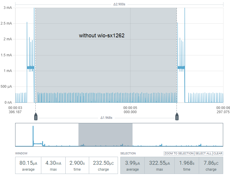
About 4uA very nice!
Now with the wio mounted and the proper radio.begin() but without radio.sleep()
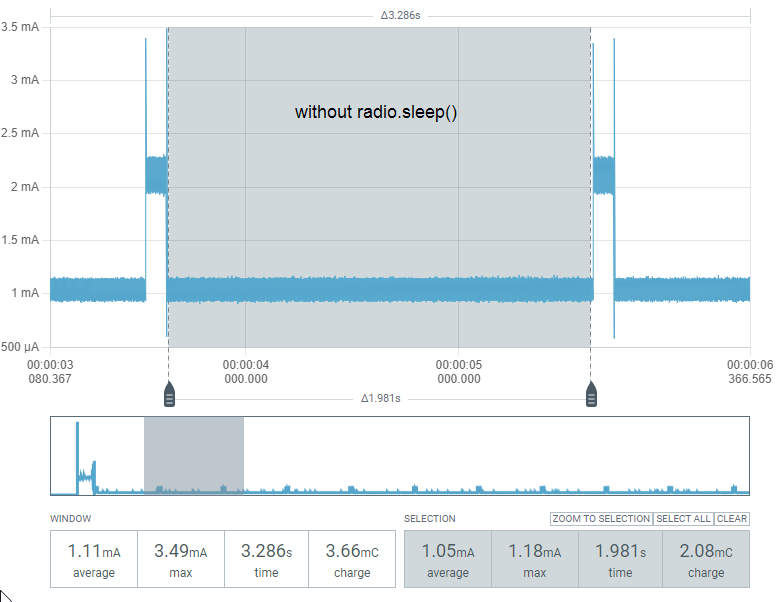
About 1mA, seems plausible since the radio is powered and idle.
But now with radio.sleep():
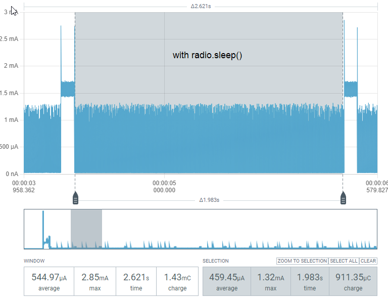
Well, this is unexpected. The consumption becomes very “noisy.” The upper range is the same as it is without radio.sleep(), but the lower range drops drastically.
After reading this, I tried pulling up the NSS-Pin with a 10K resistor, but there was no difference.
Can anyone chime in? Am I missing something obvious?