Hi there,
I want to do a new project that connects to a USB Type C plug.
My ECAD software for this project is Autodesk Eagle and I want to fabricate
it with SeeedStudio Fusion.
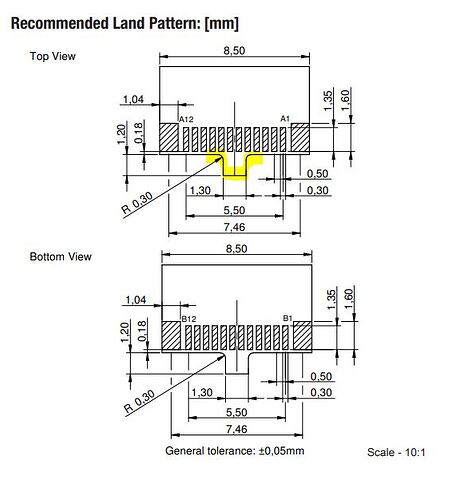
It’s intended to use the Wurth 632712000112. The required component
footprint has a rectangular protrusion with a small radius inside.
pasted from <LINK_TEXT text=“https://www.we-online.com/catalog/datas … 000112.pdf”>https://www.we-online.com/catalog/datasheet/632712000112.pdf</LINK_TEXT>
[attachment=1]112_highlight protrusion.JPG[/attachment]
I am unsure about the design of the board so that it can be manufactured
reliably.
Some key information:
The rectangle protrudes 1.2mm and is 1.3mm wide.
The inside corner radius is 0.3mm.
My thought to manufacture is:
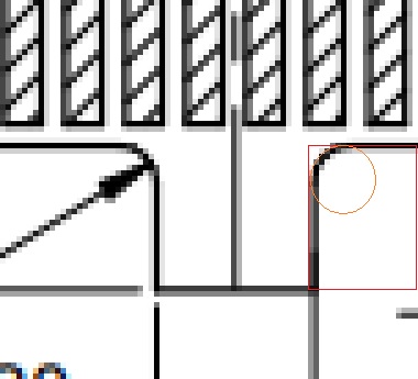
1- slot has a minimum of 1mmx1mm , the red rectangle indicates a slot but
will be wider in real life
2- the orange circle represents a hole of diameter 0.3mm
together 1 and 2 will give me the required protrusion.
[attachment=1]112_highlight protrusion.JPG[/attachment]
(Service for Fusion PCB | Seeed Studio Wiki)
Please let me know if this will work with your PCB manufacture and whether
there is a better way to achieve the same goal.
Additionally- This connector has pitch 0.5mm with a pad width of 0.3mm
(spacing of 0.2mm). I assume I need the “Minimum Solder Mask Dam” of 0.1mm
and not the default 0.4mm?

