Hi Seeed,
Sorry i posted this in the wrong forum, So reposting it here.
I just got my new DSO quad, I am using this to probe the Uart signals, So the first thing i did was using the Digital channels CH-C/D. I am able to see the Uart signals(but not v clear) so i want to change th Voltage scale, but i dont find any options to change the Voltage scale division for these channels.
I even tried to use the Analog channels A & B (setting to DC), but both channels are not able to capture these signals. Am i doing something wrong. Could anyone suggest me how to change the voltage scale on Digital channels or how to use the Analog channels to probe the Uart.
Thanks,
Cg
Does no one know how to measure Uart signals using DSO Quad or is it that the DSO Quad is totally incapable for measuring such signal.
Basically it is not a problem at all 
What exactly do you want to measure?
See one byte on the screen?
Use single shot, falling edge trigger with appropriate time scale setting; calculate the same from bit-per-second setting of the UART.
See ASCII on the DSO screen … not possible 
BW
Digital input channels are, well, digital. You cannot set a voltage scale on them since they don’t actually measure the voltage but only sense low or high level. They are directly wired to FPGA 3.3V logic input pins. The max voltage that is considered ‘low level’ and the min voltage that is considered ‘high level’ can be found in the FPGA datasheet, but they should be somewhere around 0.2V and 2V. There is discussion in other topics on how safe it is to routinely apply 5V signals to these digital channels, since the FPGA is not designed to take more than 3.3V and the external protection added to the pins is quite minimal.
What voltage level is the UART signal you want to observe?
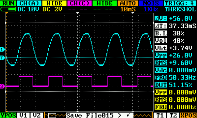
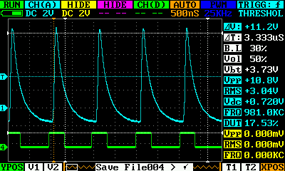
Here my experiments with digital input.
On the analog and digital canal one and the same signal is given. No problem.
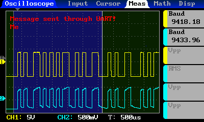
About seeing ASCII characters, in my firmware it is possible 
In the measure tab, choose “Baud rate detector” and in top left corner, it will display decoded ascii characters. It automatically identifies whether it is RS232 or TTL logic
Whole project and compiled HEX file can be found here:
https://github.com/gabonator/DS203
Gabriel