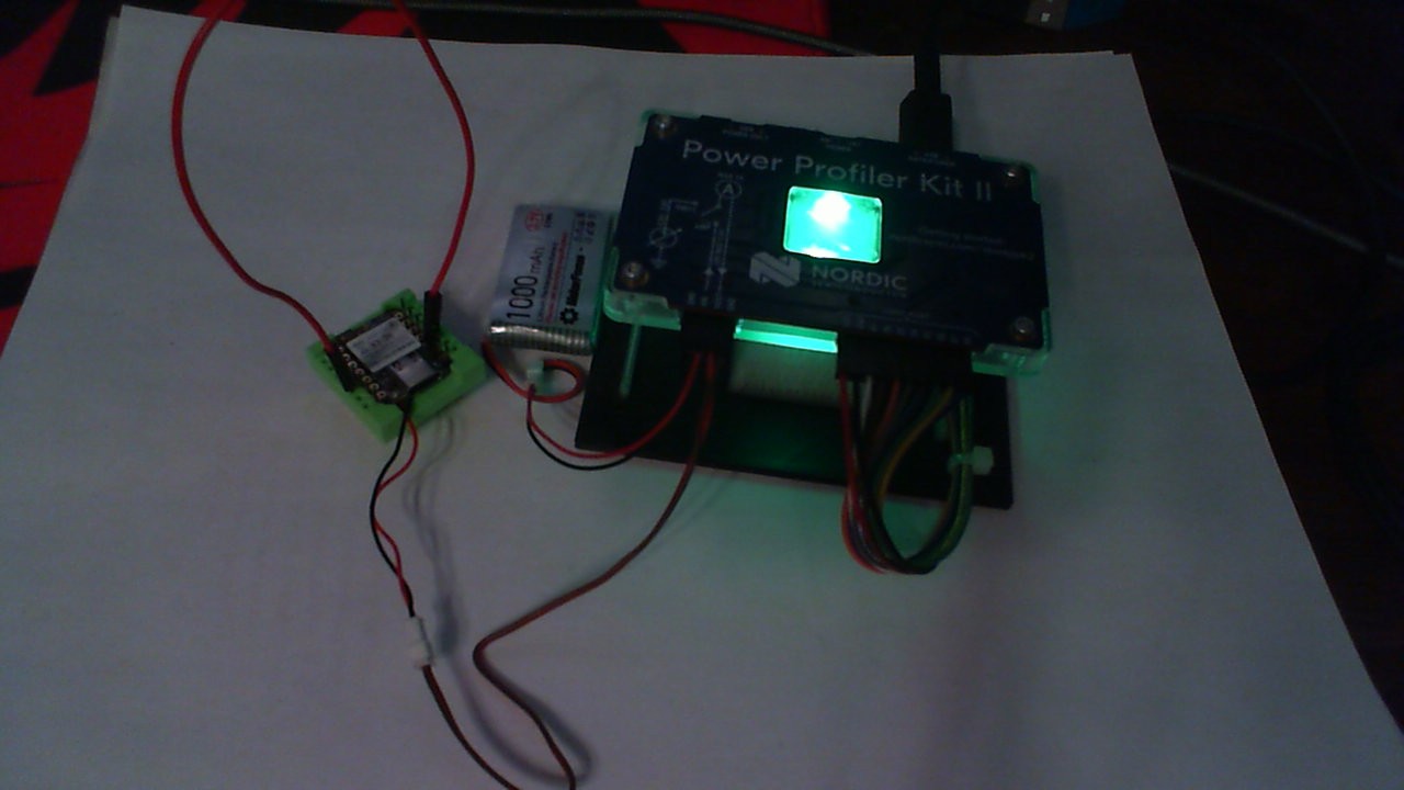
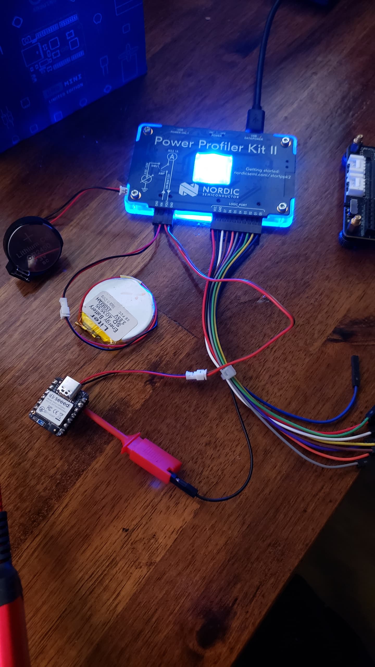
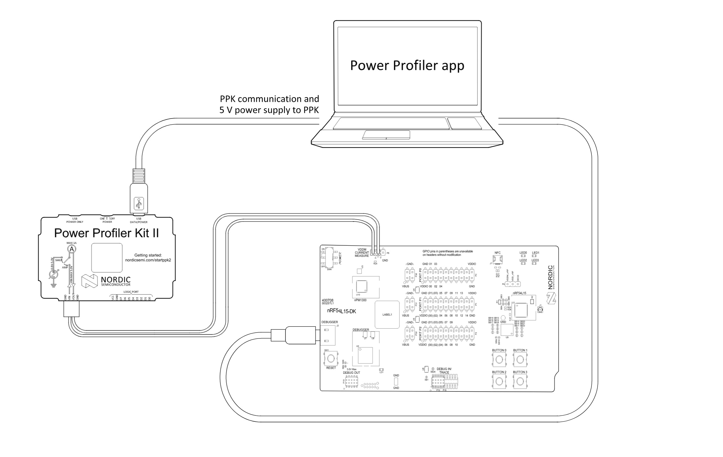
![]() SO here is a video of the power profiler from Nordic Semiconductor being used with a Xiao Device Under Test
SO here is a video of the power profiler from Nordic Semiconductor being used with a Xiao Device Under Test
this device is the Nrf52840 Sense, the video Depicts the power being consumed by the device while testing the flash and sleeping. code used is also included.

HTH
GL ![]() PJ
PJ ![]()
// 12/16/2023 Grove Expansion Board Flash Chip Test Code & OLED Display press button to SLEEP or Wake-UP
// from Adafruit_SPIFlash Example
// Author: PJG
//
//----------------------------------------------------------------------------------------------
// BSP : Seeed nRF52 Boards 1.1.1
// Board : Seeed XIAO nRF52840 Sense
// Grove Expansion Board & cheapest (I2C) SSD1306 display on AL-Gore Network & Grove push-button
//----------------------------------------------------------------------------------------------
// SdFat - Adafruit Fork@ 2.2.3 // Pay close attention to the LIB versions.
// Adafruit SPIFlash@ 4.1.3 // NOT all are compatable and New ones do NOT work
// Adafruit TinyUSB [email protected] // There are TOO MANY Flash libraries out. YMMV
//
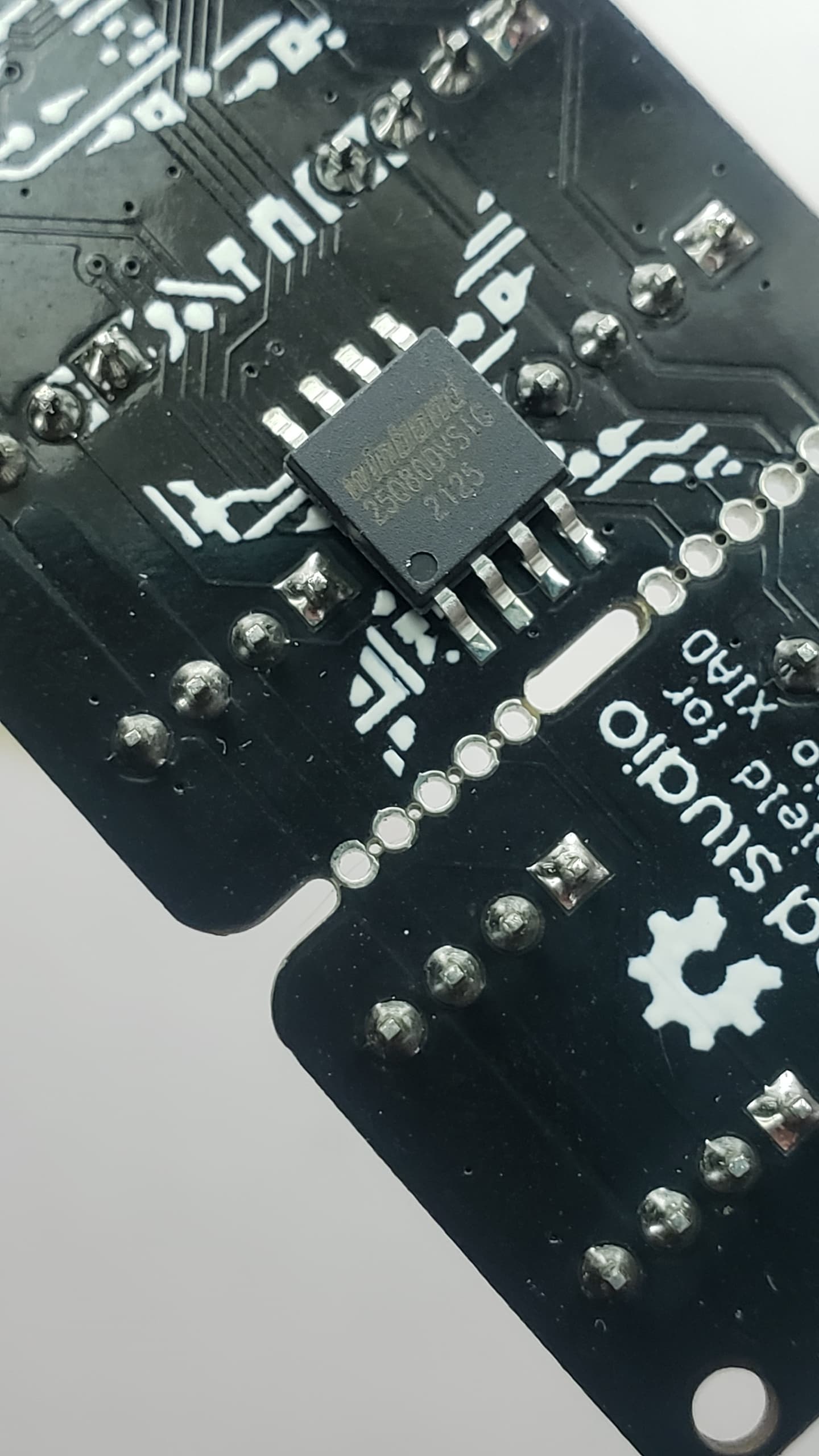
// This tests and Identifies the Onboard Xiao QSPI Flash Chip
// and Expansion Flash Chip on Grove Board that is Hardwired to A1/D1 (pin 1) on Xiao
// for the Flash chipSelect CS or SS in the code
// Adafruit_SPIFlash is set with SPI class mthod. You can mix QSPI mode and SPI class are possible.
// The trick with the Nordic Nrf52x devices is the SPI interfaces as NRF_SPIM0, NRF_SPIM1, NRF_SPIM2,
// NRF_SPIM3 for which buss. device mode or method.
// HTH
//
#include <Arduino.h>
#include <SPI.h>
#include <Wire.h>
#include <SdFat.h>
#include <Adafruit_SPIFlash.h>
#include <Adafruit_GFX.h>
#include <Adafruit_SSD1306.h>
#include <LSM6DS3.h>
// Flash Chip declerations, made up from Data Sheets.
SPIFlash_Device_t const p25q16h{
// You can Declare the chip you choose this way or add it to the flash_devices
// Configuration for W25Q80DV flash chip from the Data Sheet.
.total_size = (1UL << 21), // 2MiB
.start_up_time_us = 10000,
.manufacturer_id = 0x85,
.memory_type = 0x60,
.capacity = 0x15,
.max_clock_speed_mhz = 55,
.quad_enable_bit_mask = 0x02,
.has_sector_protection = 1,
.supports_fast_read = 1,
.supports_qspi = 1,
.supports_qspi_writes = 1,
.write_status_register_split = 1,
.single_status_byte = 0,
.is_fram = 0,
};
SPIFlash_Device_t const w25q80{
// Also seemsto be case sensative lower case preferred
// Configuration for W25Q80DV flash chip from the Data Sheet.
.total_size = (1UL << 20), // 1MiB
.start_up_time_us = 10000,
.manufacturer_id = 0xEF,
.memory_type = 0x40,
.capacity = 0x14,
.max_clock_speed_mhz = 55,
.quad_enable_bit_mask = 0x02,
.has_sector_protection = 0,
.supports_fast_read = 1,
.supports_qspi = 1,
.supports_qspi_writes = 0,
.write_status_register_split = 0,
.single_status_byte = 0,
.is_fram = 0,
};
//Create a instance of class LSM6DS3//#define int2Pin P0_11
LSM6DS3 myIMU(I2C_MODE, 0x6A); //I2C device address 0x6A // IMU
#define int2Pin PIN_LSM6DS3TR_C_INT1
#define OLED_RESET -1 //2 // Reset pin # (or -1 if sharing Arduino reset pin)
#define SCREEN_WIDTH 128 // OLED display width, in pixels
#define SCREEN_HEIGHT 32 // OLED display height, in pixels
#define clkDuring 400000UL
#define clkAfter 100000UL
// Declaration for an SSD1306 display connected to I2C (SDA, SCL pins)
Adafruit_SSD1306 display(SCREEN_WIDTH, SCREEN_HEIGHT, &Wire, OLED_RESET, clkDuring, clkAfter);
const int buttonPin = 2; // the number of the pushbutton pin
int buttonState = 0; // variable for reading the pushbutton status
uint8_t binterruptCount = 0; // Amount of received interrupts
const int BuzzerPin = 1;
int buzzer = BuzzerPin;
#define LEDR LED_BUILTIN // default
#define LEDG LED_GREEN
#define LEDB LED_BLUE
//#define LED LEDB
//#define LED P0_26 // RED
//#define LED P0_30 // GREEN
//#define LED P0_6 // BLUE
uint8_t interruptCount = 0; // Amount of received interrupts
uint8_t prevInterruptCount = 0; // Interrupt Counter from last loop
bool first10LoopCompleted = false;
#define SS_SPI0 1 // default to Pin 7 if you don't declare it as the CS for the Flash Chip A1/D1 pin1 on the Xiao
#define SS_SPI1 25 // Defaul SS or CS for the Onboard QSPI Flash Chip
SPIClass SPI_2(NRF_SPIM0, PIN_QSPI_IO1, PIN_QSPI_SCK, PIN_QSPI_IO0); // Onboard QSPI Flash chip
Adafruit_FlashTransport_SPI QflashTransport(PIN_QSPI_CS, SPI_2); // CS for QSPI Flash
Adafruit_SPIFlash Qflash(&QflashTransport);
SPIClass SPI_1(NRF_SPIM3, D9, D8, D10); // MISO, SCK, MOSI /EXPANSION FLASH// CS pin D1 (hardwired)
Adafruit_FlashTransport_SPI EflashTransport(SS_SPI0, SPI_1); // Flash Type
Adafruit_SPIFlash Eflash(&EflashTransport);
// ******************** START *****************//
void setup() {
Wire.begin();
Serial.begin(9600);
delay(2500);
//while (!Serial) delay(2100); // Code will wait until USB port is plugged in.
pinMode(BuzzerPin, OUTPUT);
buzzer = LOW ; // Buzzer OFF
Serial.println();
Serial.println("Program " __FILE__ " compiled on " __DATE__ " at " __TIME__);
Serial.println();
Serial.println("Processor came out of reset.");
Serial.println();
pinMode(D6, INPUT_PULLUP); // /WP
//pinMode(D7, INPUT_PULLUP); // /HOLD
pinMode(SS_SPI0, OUTPUT); // CS for flash
digitalWrite(SS_SPI0, HIGH); // <-- Set CS pin HIGH to deselect
pinMode(buttonPin, INPUT_PULLDOWN); // initialize the pushbutton pin as an input: for GROVE PB
//attachInterrupt(digitalPinToInterrupt(buttonPin), myISR_Falling, FALLING);
attachInterrupt(digitalPinToInterrupt(buttonPin), myISR_Rising, RISING);
myIMU.settings.gyroEnabled = 0; // Gyro currently not used, disabled to save power
myIMU.begin();
pinMode(int2Pin, INPUT_PULLUP);
attachInterrupt(digitalPinToInterrupt(int2Pin), int1ISR, RISING);
setupDoubleTapInterrupt();
startsound(); //Beep Buzzer speaker on A3
setupblink(); // Tests The onboard RGB LED
Serial.println("--------------");
Serial.println(SS_SPI0);
Serial.println(MOSI); // master out, slave in
Serial.println(MISO); // master in, slave out
Serial.println(SCK); // clock
Serial.println("--------------");
//startDisplay(); //Serial.println("SSD1306 allocation worked");
Serial.println("Flash Testing Now.");
Serial.println("Onboard QSPI Flash Testing");
Serial.println(F("QSPI Flash ID P25Q16H"));
//flashtestDisplay();
// Initialize QSPI flash library and check its chip ID.
if (!Qflash.begin(&p25q16h, 1)) {
Serial.println(F("Error, failed to initialize QSPI flash chip!"));
// while (1)
;
}
Serial.print(F("QFlash chip JEDEC ID: 0x"));
Serial.println(Qflash.getJEDECID(), HEX);
Serial.print(F("Flash size: "));
Serial.print(Qflash.size() / 1024);
Serial.println(F(" KB"));
Serial.println(F("QFlash chip successfully ID'd!"));
delay(1000);
Serial.println(); // Keep Display the Same
Serial.println("Expansion Flash testing!!");
//digitalWrite(SS_SPI0, HIGH); // <-- Set CS pin HIGH to deselect
Serial.println(F("SPI Flash ID W25Q80DV"));
// Initialize W25Q80DV flash library and check its chip ID.
if (!Eflash.begin(&w25q80,1)) {
Serial.println(F("Error, failed to initialize W25Q80DV flash chip!"));
while (1)
;
}
Serial.print(F("W25Q80DV chip JEDEC ID: 0x"));
Serial.println(Eflash.getJEDECID(), HEX);
Serial.print(F("Flash size: "));
Serial.print(Eflash.size() / 1024);
Serial.println(F(" KB"));
Serial.println(F("SPI Flash chip successfully ID'd!"));
delay(1000);
if (!display.begin(SSD1306_SWITCHCAPVCC, 0x3C)) { // Address 0x3C for 128x32
Serial.println("SSD1306 allocation failed");
}
delay(1000);
startDisplay();
flashtestDisplay();
//delay (30000);
//sd_power_system_off();
//NRF_POWER->SYSTEMOFF = 1;
}
// **END of SETUP **//
void loop() {
delay(250);
digitalWrite(LED_BUILTIN, true);
delay(500);
digitalWrite(LED_BUILTIN, false);
delay(500);
if (first10LoopCompleted == true) {
testTheflash();
} else
display.clearDisplay();
display.setTextSize(1); // Normal 1:1 pixel scale
display.setTextColor(WHITE); // Draw white text
display.setCursor(0, 0); // Start at top-left corner
display.display();
//display.clearDisplay();
//display.display();// Your code here
buttonState = digitalRead(buttonPin); // read the state of the pushbutton value:
if (buttonState == HIGH) {
display.clearDisplay();
display.setTextSize(1); // Normal 1:1 pixel scale
display.setTextColor(WHITE); // Draw white text
display.setCursor(0, 0); // Start at top-left corner
display.display(); // Go do it.
display.println(" SLEEP ");
display.display();
delay(2000);
Serial.println("SLEEP/WAKE Button Pushed");
delay(2000);
menuMan();
goToPowerOff();
} else {
buttonState = LOW;
//menuMan();
}
delay(1500);
buttonState = digitalRead(buttonPin); // read the state of the pushbutton value:
display.clearDisplay();
display.setTextSize(2); // Normal 1:1 pixel scale
display.setTextColor(WHITE); // Draw white text
display.setCursor(10, 8); // Start at top-left corner
display.display(); // Go do it.
display.println(" Idle.... ");
display.display();
delay(1000);
display.setTextSize(2); // Normal 1:1 pixel scale
display.setTextColor(BLACK); // Draw white text
display.setCursor(10, 8); // Start at top-left corner
display.display(); // Go do it.
display.println(" Idle.... ");
display.display();
delay(1000);
display.setTextSize(1); // Normal 1:1 pixel scale
display.setTextColor(WHITE); // Draw white text
display.setCursor(10, 8); // Start at top-left corner
//display.display();
display.println(" POWER SAVE ");
display.display();
delay(500); // Go do it.
Serial.println("SOFT DEVICE “SYSTEM ON” POWER SAVE");
delay(1000);
sd_power_mode_set(NRF_POWER_MODE_LOWPWR);
sd_power_dcdc_mode_set(NRF_POWER_DCDC_ENABLE);
__WFE();
__WFI();
sd_app_evt_wait(); //SOFT DEVICE “SYSTEM ON” POWER SAVE
delay(100);
}
//END//
void myISR_Falling() { // Pressed Button Interrupt //
binterruptCount++;
buttonState = HIGH;
}
void myISR_Rising() { // Pressed Button Interrupt //
binterruptCount++;
buttonState = HIGH;
}
//
// Functions *****************************************************
//
void startDisplay() {
pinMode(LED_RED, OUTPUT); // initialize the LED pin as an output:
pinMode(LED_GREEN, OUTPUT); // initialize the LED pin as an output:
pinMode(LED_BLUE, OUTPUT);
pinMode(LED_BUILTIN, OUTPUT); // initialize the LED pin as an output:
display.clearDisplay();
display.setTextSize(1); // Normal 1:1 pixel scale
display.setTextColor(WHITE); // Draw white text
display.setCursor(0, 0); // Start at top-left corner
display.display(); // Go do it.
display.println("Display (StartUp)");
display.display();
delay(500);
display.clearDisplay();
display.setCursor(0, 0);
display.println("Power ON ");
delay(1000);
display.setCursor(0, 10);
display.print("Flash Test:\n"); //Flash Test:0123456789
display.display();
delay(1500);
}
void flashtestDisplay() {
display.setCursor(68, 10);
display.print("--");
display.display();
delay(250);
display.print("---");
display.display();
delay(250);
display.print("---");
display.display();
delay(250);
display.print("--");
display.display();
delay(500);
first10LoopCompleted = true;
}
void menuMan() {
display.setTextSize(1); // Normal 1:1 pixel scale
display.setTextColor(WHITE); // Draw white text
display.setCursor(0, 0);
if (first10LoopCompleted = false) {
display.println("Power ON ");
display.display();
delay(500);
}
display.setCursor(0, 10);
display.print("Flash Test:\n"); //Flash Test:0123456789
display.display();
delay(100);
display.clearDisplay();
display.display();
display.setCursor(12, 10);
display.print("PASS:");
display.print(Qflash.size() / 1024);
display.println(F(" KB"));
display.display();
delay(500);
display.setCursor(12, 18);
display.print("PASS:");
display.print(Eflash.size() / 1024);
display.println(F(" KB"));
display.display();
delay(250);
display.clearDisplay();
display.display();
}
void testTheflash() {
display.setTextColor(WHITE); // Draw white text
display.setTextSize(1);
display.setCursor(4, 22);
display.print("P25Q16H "); // turn ON
display.display();
delay(500);
display.setTextSize(2);
display.setCursor(63, 18);
display.print(" PASS");
display.display();
delay(500);
display.setTextSize(1);
display.setTextColor(BLACK); // turn Off
display.setCursor(4, 22);
display.print("P25Q16H ");
display.display();
delay(500);
display.setCursor(63, 18);
display.setTextSize(2);
display.print(" PASS");
display.display();
delay(250);
display.setTextColor(BLACK);
display.setCursor(63, 18);
display.setTextSize(2);
display.print(" PASS");
display.display();
delay(250);
display.setCursor(4, 22);
display.setTextSize(1);
display.print("P25Q16H ");
display.display();
delay(500);
display.setCursor(68, 10);
display.setTextSize(1);
display.print("**********");
display.display();
delay(500);
display.setTextColor(WHITE); // Draw white text
display.setCursor(4, 22);
display.print("W25Q80DV");
display.display();
delay(500);
display.setCursor(68, 10);
display.print("--");
display.display();
delay(500);
display.print("---");
display.display();
delay(500);
display.print("---");
display.display();
delay(500);
display.print("--");
display.display();
delay(500);
display.setCursor(63, 18);
display.setTextSize(2);
display.print(" PASS");
display.display();
delay(1000);
display.setTextColor(BLACK);
display.setCursor(4, 22);
display.setTextSize(1);
display.print("W25Q80DV");
display.display();
delay(500);
first10LoopCompleted = false;
}
void setupblink() {
setLedRGB(false, true, false); // Red
delay(1000);
setLedRGB(true, false, false); // Green
delay(1000);
setLedRGB(false, false, true); // Blue
delay(1000);
setLedRGB(false, false, false); // OFF
}
void setLedRGB(bool red, bool green, bool blue) {
if (!blue) {
digitalWrite(LEDB, HIGH); } else { digitalWrite(LEDB, LOW); }
if (!green) {
digitalWrite(LEDG, HIGH); } else { digitalWrite(LEDG, LOW); }
if (!red) {
digitalWrite(LEDR, HIGH); } else { digitalWrite(LEDR, LOW); }
}
void startsound() {
tone(buzzer, 890);
delay(220);
noTone(buzzer);
delay(20);
tone(buzzer, 800);
delay(220);
noTone(buzzer);
delay(20);
tone(buzzer, 800);
delay(220);
noTone(buzzer);
delay(20);
tone(buzzer, 990);
delay(420);
noTone(buzzer);
delay(20);
}
void setupDoubleTapInterrupt() {
uint8_t error = 0;
uint8_t dataToWrite = 0;
// Double Tap Config
myIMU.writeRegister(LSM6DS3_ACC_GYRO_CTRL1_XL, 0x60); //* Acc = 416Hz (High-Performance mode)// Turn on the accelerometer ODR_XL = 416 Hz, FS_XL = 2g
myIMU.writeRegister(LSM6DS3_ACC_GYRO_TAP_CFG1, 0x8E); // INTERRUPTS_ENABLE, SLOPE_FDS// Enable interrupts and tap detection on X, Y, Z-axis
myIMU.writeRegister(LSM6DS3_ACC_GYRO_TAP_THS_6D, 0x03); // was 85 Set tap threshold 8C
myIMU.writeRegister(LSM6DS3_ACC_GYRO_INT_DUR2, 0x7F); // Set Duration, Quiet and Shock time windows 7F
myIMU.writeRegister(LSM6DS3_ACC_GYRO_WAKE_UP_THS, 0x80); // Single & double-tap enabled (SINGLE_DOUBLE_TAP = 1)
myIMU.writeRegister(LSM6DS3_ACC_GYRO_MD1_CFG, 0x08); // Double-tap interrupt driven to INT1 pin
}
void int1ISR() {
interruptCount++;
;
}
void goToPowerOff() {
//sleepFlash();
setLedRGB(false, false, false);
Serial.println("Going to SLEEP System OFF Tap to WAKE \n");
display.clearDisplay();
display.setCursor(10, 8);
display.setTextSize(3);
display.print("SLEEP");
display.display();
delay(500);
display.clearDisplay();
display.display();
setupDoubleTapInterrupt(); // not needed here, if already applied..
delay(2000); // delay seems important to apply settings, before going to System OFF
//Ensure interrupt pin from IMU is set to wake up device
// nrf_gpio_cfg_sense_input(digitalPinToInterrupt(int2Pin), NRF_GPIO_PIN_PULLDOWN, NRF_GPIO_PIN_SENSE_HIGH);
delay(2000); // delay seems important to apply settings, before going to System OFF
uint32_t pin = D2;
pin = g_ADigitalPinMap[pin];
nrf_gpio_cfg_sense_input(pin, NRF_GPIO_PIN_PULLDOWN, NRF_GPIO_PIN_SENSE_HIGH);
delay(2000); //15 seconds before turns off (if USB is plugged in, that circuit will still draw 2mA)
Serial.println(" You're NOT doing anything, I'll Sleep.");
delay(2000);
sd_power_system_off();
NRF_POWER->SYSTEMOFF = 1;
}
and the 2nd test set is Chip with onboard Flash Only no other buttons or displays, this @msfujino code set.
//----------------------------------------------------------------------------------------------
// BSP : Seeed nRF52 Borads 1.1.8
// Board : Seeed nRF52 Borads / Seeed XIAO nRF52840 Sense
//----------------------------------------------------------------------------------------------
// See datasheet "6.10.2 Port event"
// In order to prevent spurious interrupts from the PORT event while configuring the sources, the user
// shall first disable interrupts on the PORT event (through INTENCLR.PORT), then configure the sources
// (PIN_CNF[n].SENSE), clear any potential event that could have occurred during configuration
// (write '0' to EVENTS_PORT), and finally enable interrupts (through INTENSET.PORT).

// 2025/01/21

#include <Adafruit_SPIFlash.h>    // 5.0.0, NOTE:need to deleted /Documents/Arduino/libraries/SdFat
#include <flash_devices.h>
SPIFlash_Device_t const p25q16h {   // You can Declare the chip you choose this way or add it to the flash_devices
  // Configuration for p25q16h flash chip from the Data Sheet.
  .total_size = (1UL << 21), // 2MiB
  .start_up_time_us = 10000,
  .manufacturer_id = 0x85,
  .memory_type = 0x60,
  .capacity = 0x15,
  .max_clock_speed_mhz = 55,
  .quad_enable_bit_mask = 0x02,
  .has_sector_protection = 1,
  .supports_fast_read = 1,
  .supports_qspi = 1,
  .supports_qspi_writes = 1,
  .write_status_register_split = 1,
  .single_status_byte = 0,
  .is_fram = 0,
};
SPIFlash_Device_t const w25q80 {  // Also seemsto be case sensative lower case preferred
  // Configuration for W25Q80DV flash chip from the Data Sheet.
  .total_size = (1UL << 20), // 1MiB
  .start_up_time_us = 5000,
  .manufacturer_id = 0xEF,
  .memory_type = 0x40,
  .capacity = 0x14,
  .max_clock_speed_mhz = 104,
  .quad_enable_bit_mask = 0x02,
  .has_sector_protection = 0,
  .supports_fast_read = 1,
  .supports_qspi = 1,
  .supports_qspi_writes = 0,
  .write_status_register_split = 0,
  .single_status_byte = 0,
  .is_fram = 0,
};

// for flashTransport definition
Adafruit_FlashTransport_QSPI flashTransport;
Adafruit_SPIFlash flash(&flashTransport);
static const SPIFlash_Device_t my_flash_devices[] = {p25q16h,};
const int flashDevices = 1;

#define PIN_WAKEUP (28)  // D0:(2), D1:(3), D2:(28), D3:(29), D4:(4), D5(5), D6(43), D7(44), D8(45), D9(46), D10(47)

void setup()
{
  // Enable DC-DC converter Mode
  NRF_POWER->DCDCEN = 1;            // Enable DC/DC converter for REG1 stage

  // on board Flash enter to Deep Power-Down Mode
  flash.begin(my_flash_devices, flashDevices);
  flashTransport.begin();
  flashTransport.runCommand(0xB9);  // enter deep power-down mode
  delayMicroseconds(5);             // tDP=3uS
  flashTransport.end();

  // LED on for 1 sec.
  digitalWrite(LED_GREEN, LOW);
  delay(1000);
  digitalWrite(LED_GREEN, HIGH);

// https://forum.seeedstudio.com/t/xiao-ble-long-boot-up-time/280116/13
//  NRF_POWER->GPREGRET = 0x6D; // Option : Set GPREGRET0 to 0x6D (DFU SKIP)

  NRF_GPIOTE->INTENCLR |= 0x80000000;   // disable interrupt for event PORT
//  nrf_gpio_cfg_sense_input(PIN_WAKEUP, NRF_GPIO_PIN_PULLDOWN, NRF_GPIO_PIN_SENSE_HIGH);  // configure gpio for wakeup event
  nrf_gpio_cfg_sense_input(PIN_WAKEUP, NRF_GPIO_PIN_PULLUP, NRF_GPIO_PIN_SENSE_LOW);  // configure gpio for wakeup event
  NRF_GPIOTE->EVENTS_PORT = 0;          // Event not generated
  NRF_GPIOTE->INTENSET |= 0x80000000;   // enable interrupt for event PORT

  // enter to Deep Sleep Mode
  NRF_POWER->SYSTEMOFF = 1;
}

void loop()
{
}