I’ve got two CAN-shields and an Arduino UNO in my hand and I wonder if it’s possible to make both shields work on one Arduino. 
Can you give me a help with the wiring and programming?
I want to receive messages with one shield, log or edit some messages and re-send them with the other shield.
if you just want to receive message with one shield, log or edit some message and re-send them with the other shield, I don’t think you need two shield~
Actually, one is enough. ![]()
Or you can let me know more about you plan, then I can confirm that~
What I plan to do is a little different ![]() : I want to read messages on one bus with the first shield, filter out some messages and re-send the rest on a second bus with the second shield:
: I want to read messages on one bus with the first shield, filter out some messages and re-send the rest on a second bus with the second shield:
----BUS1----> ||SHIELD1||-->||Arduino||-->||Shield2||---->BUS2----What I need to know is what I have to change in the wiring (CS!) or in the library to support two shields.
Ok~ you have 2 things to do.
you can see here
, what you should is cut the connect of one shield, the connect it to D9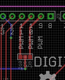
then one cs is D10 and the other is D9
when you control the D10 shield , add this code:
digitalWrite(9, HIGH);
digitalWrite(10, LOW);
and when use the D9 sheild, add this code:
digitalWrite(10, HIGH);
digitalWrite(9, LOW);
just have a try, if any question please contract me asap~ ![]()
Thanks, but it seems another problem came up:
I’ve bought the two shields together with an Arduino Leonardo (an Itead Leonardo, to be precise). The Leonardo doesn’t have the SPI bus on pins 11-13, but only on the ICSP header. The shield needs has SPI the old Uno way. So I’ve wired the Leonardo and one CAN-Shield in the following way:
Leonardo digital pin 10 <-> Shield pin 10
Leonardo ICSP MOSI <-> Shield pin 11
Leonardo ICSP MISO <-> Shield pin 12
Leonardo ICSP SCK <-> Shield pin 13
Leonardo 5V <-> Shield 5V Pin on the Power rail
Leonardo digital pin 3 <-> Shield pin 2 (INT 0)
I’ve connected CAN-H and CAN-L to a CAN-USB interface which is capable of sending and receiving arbitrary messages.
After uploading the “send” project from the examples folder, the red TX LED is dimmed on (despite the 100 ms delay in loop()).
The “receive” example doesn’t light up the TX LED.
Any thoughts what might be wrong?
Actually I had never try to use a Leonardo with a Canbus Shield, but it should work.
and, does it any Serial print in the terminal ? such as “CAN INIT OK” or something else~
Hello loovee,
I am trying to stack a CAN-bus shield together with a WiFi Shield on an Arduino UNO R3. The thing is, they both use pin 10 for SS/CS. To start I am just trying with only my CAN-bus shield connected to the UNO and trying to get the communication working using another pin for the SS/CS than pin 10. On the Hardware side it is not a big problem, but I am a bit lost on the Software side.
You said that I should put the following in my code:
digitalWrite(10, HIGH);
digitalWrite(9, LOW);But where exactly do I have to put this? And I do not really understand what this changes to the behavior of the SPI bus.
I thought I had to change “#define SPICS 10” into “#define SPICS 9” in the library file “mcp_can_dfs.h”. But after doing this it is not working anymore. If I reconnect it to pin 10, like it originally was, it also is not working anymore, which means the change is doing something,… but it seems that this is not enough to get pin 9 working as the SS/CS pin,…
I really need some help here ![]()
Thank you.
Anyone reading this seeking to move the chip_select pin from 10 to 9 on the CAN_shield will need to modify the “#define SPICS” parameter in the “mpc_can_dfs.h” file located in the CAN_Shield/MCP2515_lib library folder.
You will then need to add the following code before SPI.begin and/or CAN.begin and the library will handle the rest:
pinMode(9, OUTPUT);
digitalWrite(9, HIGH);   // Define IO state to a known level to make sure the MCP2515 is unselected before initiating both SPI and CAN.
CAN.begin(SOME_BAUD_RATE);
// The rest of the magic stuff