Hello, some time ago I tried to produce manufacturing files for seeedstudio. My school has a cnc-pcb cutter, and I thought the process would be the same. That was not the case. This is a guide of how to set up Altium Designer to export gerber files and drill files that seeed propagate can use with no hassle.
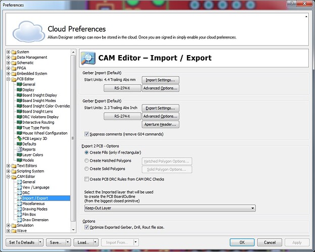
- Setup Altium Designer to export RS-274-X formatted gerber files.
- Go to Tools - Preferences
- In the preferences options, open CAM editor and click on Import/Export
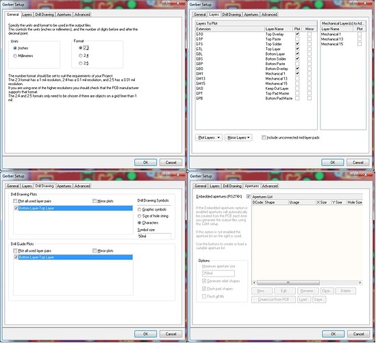
- Clicking the settings edits them
- Go to File - Fabrication Outputs - Gerber Files
- Read the quote furter down from seeedstudio on what files to export - this tells what to export.
- Use a mechanical layer as board outline. I use mechanical 1.
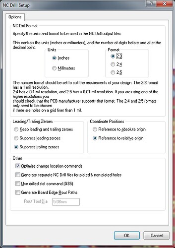
- Now for the drill files. This was the step I had problems with.
- Go to File - Fabrication Outputs - NC Drill files
- After hitting ok, you will be prompted to generate the files - simply click ok.
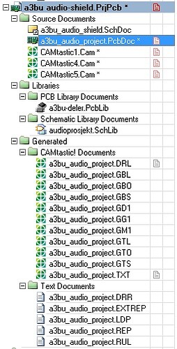
- Now, these files have been generated. (The ones under Generated - “Text documents” and “CAMtastic! documents”)
- Right click on one file, select Explore - you should find all the generated files.
- Zip all of these files, send them to manufacturing.
There are certainly some files that are not needed. Possibly if Seeed could comment on what is needed and not?
From seeedstudios own gerber generation page: I’m not allowed to link, new user. You can find the page from the manufacturing specs on the PCB-propagate info.
Especially this last part is a bit confusing if you are generating with Altium Designer. And yes, the .DRL gerber file that is generated with the NC drill generation do appear empty, but it is definitely needed.
I hope this is of some help for anyone trying to export files for manufacturing with Altium Designer. There are improvements to this guide, especially the number of files being sent.
Thanks again to Shuyang at shuyang @ seeedstudio . com for helping me with the validation of the files I generated.


