Hi there,
OK So I figured it out with some Open AI hep >>>>LOL 
So I started with the LED light and Switch Examples The Boot button turns the Xiao C6 LED “LIGHT” On/Off " it’s the ZigBee (EndPoint) from the Switch which is the (coordinator).
Once they both worked and connected and I confirmed the ZigBee Stack was init’d and the connection was working (i could press the button and observe the LED go on & Off).
Next,
I opened the Temperature Sensor Example & the corresponding Thermostat Example.
I see that I could just stuff a IMU reading in there and see if that would work… Spoiler ALERT it Does… Sort off.
IMU sends 3 parameters X,Y,& Z and the Temp is C/F only one set so I opted for just sending the X axis IMU data.
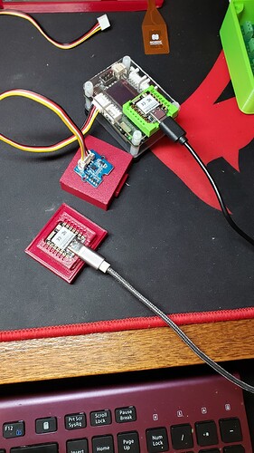
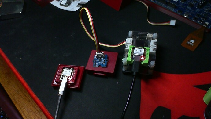
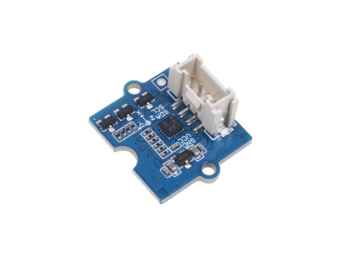
So I busted out a Grove IMU (LIS3DHTR) and plugged it into the dev board I2C port (see picture) I ran a quick example from the Wiki to verify it works, THIS ONE and it does… it prints out the X, Y, Z. and works on the C6 AOK.
connected this way (see pic) I added the echo to the Sensor end and the Thermostat end prints it out the local serial port once received from the Zigbee Sensor end. You can push the boot button to get an instant reading otherwise it sends them every 10 seconds or unless the delta on X axis changes greater than by 2… Pretty slick.
This is a cludge because arduino ZigBee espresso LIBrary doesn’t bring a lot to the table if you get my drift. but the concept “OP’s” original does work and can be performed.
HTH now here is the code… I used to Fresh Xiao ESP32C6 with BSP 3.0.6 I opened the examples and pasted my edits in so not to mess with the links in the IDE and example files, (often creating a New Sketch will break it, better to cut and paste into the originals , IMHO!)
Anyway one Xiao is on com port 12 the other is on com port 14. I do a SAVE AS after everything is working and I’m satisfied it works.i.e ZigBee_temperature_Sensor.ino , is now ZigBee_temperature_Sensor_IMU.ino
fyi;
Someone with too much time on there hands can build a ZIgBee IMU sensor EndPoint and use this as a baseline for the Coordinator to Display it or just send it out the serial port as I am.
// Zigbee IMU send data demo modified from the Temp example by PJ Glasso
// all the same ZigBee caveats apply with the tools menu, etc.
// This will read a grove connected IMU sensor and send the X,Y,& Z data out of the Serial port locally
// It will send the X axis data as the ZigBee temperature Sensor.
// Xiao ESP32C6 was used and BSP 3.0.6 installed.
//
// ZiGbee is Fast and efficiant so compatabilty and ease to build will be deciding factors, IMO
// GL 12/08/2024
//
#ifndef ZIGBEE_MODE_ED
#error "Zigbee coordinator mode is not selected in Tools->Zigbee mode"
#endif

#include "ZigbeeCore.h"
#include "ep/ZigbeeTempSensor.h"
#include <Wire.h>
#include "LIS3DHTR.h"

#define BUTTON_PIN                  9  // Boot button for C6/H2
#define IMU_SENSOR_ENDPOINT_NUMBER  10

// Initialize the LIS3DHTR sensor
LIS3DHTR<TwoWire> LIS;
#define WIRE Wire

// Define the Zigbee endpoint for the IMU sensor
ZigbeeTempSensor zbIMUSensor = ZigbeeTempSensor(IMU_SENSOR_ENDPOINT_NUMBER);

/************************ IMU sensor *****************************/
// Function to read IMU data and update Zigbee endpoint
static void imu_sensor_value_update(void *arg) {
  for (;;) {
    // Read accelerometer data from the LIS3DHTR sensor
    float ax = LIS.getAccelerationX(); // X-axis acceleration
    float ay = LIS.getAccelerationY(); // Y-axis acceleration
    float az = LIS.getAccelerationZ(); // Z-axis acceleration

    // Output IMU data to Serial (you can monitor it for debugging)
    Serial.print("IMU sensor X: "); Serial.print(ax);
    Serial.print(", Y: "); Serial.print(ay);
    Serial.print(", Z: "); Serial.println(az);

    // Update the IMU X-axis value in the Zigbee endpoint (replace "temperature" with IMU data context)
    zbIMUSensor.setTemperature(ax);  // Use X-axis acceleration for reporting

    // Uncomment below lines to experiment with Y and Z axes
    // zbIMUSensor.setTemperature(ay);  // Use Y-axis acceleration
    // zbIMUSensor.setTemperature(az);  // Use Z-axis acceleration

    delay(1000); // Delay between updates
  }
}

/********************* Arduino functions **************************/
void setup() {
  Serial.begin(115200);
  while (!Serial) {
    delay(10);
  }

  // Init button switch
  pinMode(BUTTON_PIN, INPUT);

  // Initialize the LIS3DHTR sensor
  Wire.begin();
  LIS.begin(WIRE, 0x19);  // Set I2C address of the sensor (0x19)
  LIS.openTemp();          // Turn off temperature detection (optional)
  delay(100);

  // Set the full-scale range and data rate for the LIS3DHTR sensor
  LIS.setFullScaleRange(LIS3DHTR_RANGE_2G);
  LIS.setOutputDataRate(LIS3DHTR_DATARATE_50HZ);  // Set output data rate

  // Optional: set Zigbee device name and model
  zbIMUSensor.setManufacturerAndModel("Espressif", "ZigbeeIMUSensor");

  // Set tolerance for IMU sensor values (previously used for temperature)
  zbIMUSensor.setTolerance(0.01);

  // Add endpoint to Zigbee Core
  Zigbee.addEndpoint(&zbIMUSensor);

  // When all EPs are registered, start Zigbee in End Device mode
  Zigbee.begin();

  // Start IMU sensor reading task
  xTaskCreate(imu_sensor_value_update, "imu_sensor_update", 2048, NULL, 10, NULL);

  // Set reporting interval for IMU measurements in seconds
  zbIMUSensor.setReporting(1, 0, 0.1); // Reporting every 0.1 seconds
}

void loop() {
  // Checking button for factory reset
  if (digitalRead(BUTTON_PIN) == LOW) {  // Push button pressed
    // Key debounce handling
    delay(100);
    int startTime = millis();
    while (digitalRead(BUTTON_PIN) == LOW) {
      delay(50);
      if ((millis() - startTime) > 3000) {
        // If key pressed for more than 3 secs, factory reset Zigbee and reboot
        Serial.printf("Resetting Zigbee to factory settings, reboot.\n");
        Zigbee.factoryReset();
      }
    }
    zbIMUSensor.reportTemperature(); // Trigger immediate reporting of the X-axis value
  }
  delay(100);
}
Serial OUTPUT;
ESP-ROM:esp32c6-20220919
Build:Sep 19 2022
rst:0xc (SW_CPU),boot:0x5f (SPI_FAST_FLASH_BOOT)
Saved PC:0x4001975a
SPIWP:0xee
mode:DIO, clock div:2
load:0x4086c410,len:0xcf8
load:0x4086e610,len:0x2e30
load:0x40875728,len:0x113c
entry 0x4086c410
[   268][I][esp32-hal-i2c.c:112] i2cInit(): Initializing I2C Master: sda=22 scl=23 freq=100000
[   276][W][Wire.cpp:296] begin(): Bus already started in Master Mode.
[  1273][I][ZigbeeCore.cpp:109] zigbeeInit(): List of registered Zigbee EPs:
[  1280][I][ZigbeeCore.cpp:111] zigbeeInit(): Device type: Temperature Sensor, Endpoint: 10, Device ID: 0x0302
IMU sensor X: 0.14, Y: 0.82, Z: 0.56
[  1370][I][ZigbeeCore.cpp:179] esp_zb_app_signal_handler(): Zigbee stack initialized
IMU sensor X: 0.14, Y: 0.82, Z: 0.55
IMU sensor X: 0.13, Y: 0.81, Z: 0.46
[  3726][I][ZigbeeCore.cpp:185] esp_zb_app_signal_handler(): Device started up in non factory-reset mode
[  3735][I][ZigbeeCore.cpp:198] esp_zb_app_signal_handler(): Device rebooted
IMU sensor X: 0.21, Y: 0.52, Z: 0.82
IMU sensor X: 0.22, Y: 0.51, Z: 0.85
IMU sensor X: 0.22, Y: 0.53, Z: 0.84
IMU sensor X: 0.22, Y: 0.52, Z: 0.82
IMU sensor X: 0.22, Y: 0.53, Z: 0.84
IMU sensor X: 0.23, Y: 0.51, Z: 0.75
IMU sensor X: 0.24, Y: 0.53, Z: 0.83
IMU sensor X: 0.23, Y: 0.53, Z: 0.83
IMU sensor X: -0.14, Y: 1.11, Z: 0.29
IMU sensor X: -0.14, Y: 0.06, Z: -0.92
IMU sensor X: -0.17, Y: 0.03, Z: -0.94
IMU sensor X: -0.24, Y: 0.52, Z: 0.88
IMU sensor X: 0.13, Y: 0.61, Z: 0.80
IMU sensor X: 0.16, Y: 0.61, Z: 0.78
IMU sensor X: 0.17, Y: 0.61, Z: 0.78
IMU sensor X: 0.18, Y: 0.62, Z: 0.78
IMU sensor X: 0.42, Y: 0.59, Z: 1.46
IMU sensor X: -0.18, Y: 0.13, Z: -0.92
IMU sensor X: -0.17, Y: 0.09, Z: -0.96
IMU sensor X: -0.20, Y: 0.15, Z: -0.95
IMU sensor X: 0.10, Y: 0.70, Z: 0.69
IMU sensor X: 0.08, Y: 0.72, Z: 0.70
IMU sensor X: 0.10, Y: 0.70, Z: 0.69
ThermoStat end…
// Zigbee IMU send data demo modified from the Arduino ZigBee Temp & Thermo example
// all the same ZigBee caveats apply with the tools menu, etc.
// This will read a grove connected IMU sensor as Temperature DATA from the X Axis of the remote IMU , echos the data out to the Serial port locally
// It will recieve the X axis data as the ZigBee temperature Sensor.
// Xiao ESP32C6 was used and BSP 3.0.6 installed.
//
// GL 12/08/2024 by PJ Glasso
//

#ifndef ZIGBEE_MODE_ZCZR
#error "Zigbee coordinator mode is not selected in Tools->Zigbee mode"
#endif

#include "ZigbeeCore.h"
#include "ep/ZigbeeThermostat.h"
#include <Wire.h>
#include "LIS3DHTR.h"

#define BUTTON_PIN                 9  // Boot button for C6/H2
#define IMU_SENSOR_ENDPOINT_NUMBER 5

// Initialize the LIS3DHTR sensor
LIS3DHTR<TwoWire> LIS;
#define WIRE Wire

ZigbeeThermostat zbIMUSensor = ZigbeeThermostat(IMU_SENSOR_ENDPOINT_NUMBER);

// Save IMU data
float imu_x, imu_y, imu_z;  // X, Y, Z accelerations
float imu_max_val = 10.0;  // Maximum value for the accelerometer (example range)
float imu_min_val = -10.0; // Minimum value for the accelerometer (example range)
float imu_tolerance = 0.1; // Tolerance for accelerometer data

/****************** IMU sensor handling *******************/
void receiveSensorConfig(float min_val, float max_val, float tolerance) {
    Serial.printf("IMU sensor settings: min %.2f, max %.2f, tolerance %.2f\n", min_val, max_val, tolerance);
    imu_min_val = min_val;
    imu_max_val = max_val;
    imu_tolerance = tolerance;
}

void receiveIMUData(float x_acceleration) {
    // Update accelerometer data based on received value (default is X-axis)
    imu_x = x_acceleration;

    // Optionally fetch Y and Z values if needed
    imu_y = LIS.getAccelerationY();
    imu_z = LIS.getAccelerationZ();

    // Output IMU data to Serial
    Serial.printf("Received IMU data -> X: %.2f, Y: %.2f, Z: %.2f\n", imu_x, imu_y, imu_z);
}

/********************* Arduino functions **************************/
void setup() {
    Serial.begin(115200);
    while (!Serial) {
        delay(10);
    }

    Serial.println( __FILE__ " compiled on " __DATE__ " at " __TIME__);
    Serial.println();
    Serial.println("Processor came out of reset.");

    // Init button switch
    pinMode(BUTTON_PIN, INPUT);

    // Initialize the LIS3DHTR sensor
    Wire.begin();
    LIS.begin(WIRE, 0x19);  // Set I2C address of the sensor (0x19)
    LIS.openTemp();          // Turn off temperature detection (optional)
    delay(100);

    // Set the full-scale range and data rate for the LIS3DHTR sensor
    LIS.setFullScaleRange(LIS3DHTR_RANGE_2G);
    LIS.setOutputDataRate(LIS3DHTR_DATARATE_50HZ);  // Set output data rate

    // Set callback functions for IMU data and configuration receive
    zbIMUSensor.onTempRecieve(receiveIMUData);  // X-axis acceleration as default
    zbIMUSensor.onConfigRecieve(receiveSensorConfig);

    // Optional: set Zigbee device name and model
    zbIMUSensor.setManufacturerAndModel("Espressif", "ZigbeeIMUSensor");

    // Add endpoint to Zigbee Core
    Zigbee.addEndpoint(&zbIMUSensor);

    // Open network for 180 seconds after boot
    Zigbee.setRebootOpenNetwork(180);

    // Start Zigbee with ZIGBEE_COORDINATOR mode
    Zigbee.begin(ZIGBEE_COORDINATOR);

    Serial.println("Waiting for IMU sensor to bind to the coordinator...");

    // Wait for the sensor to bind
    while (!zbIMUSensor.isBound()) {
        Serial.print(".");
        delay(500);
    }
    Serial.println("\nIMU sensor bound successfully.");

    // Get IMU sensor configuration
    zbIMUSensor.getSensorSettings();
}

void loop() {
    // Handle button switch for testing reporting intervals
    if (digitalRead(BUTTON_PIN) == LOW) {  // Push button pressed
        // Key debounce handling
        while (digitalRead(BUTTON_PIN) == LOW) {
            delay(50);
        }

        // Set reporting interval for IMU sensor
        zbIMUSensor.setTemperatureReporting(0, 10, 2);  // Set reporting interval (example)
    }

    // Print IMU sensor data every 10 seconds
    static uint32_t last_print = 0;
    if (millis() - last_print > 10000) {
        last_print = millis();

        // Request and print IMU data to Serial
        receiveIMUData(imu_x);  // Using last received X-axis value
    }
}
Serial output, Note the X axis data and when I pick up the IMU in My hand and flip it over(upside_down)
C:\Users\Dude\AppData\Local\Temp\.arduinoIDE-unsaved2024118-29344-wxmxhc.b8mh\Zigbee_Thermostat\Zigbee_Thermostat.ino compiled on Dec  8 2024 at 17:59:36

Processor came out of reset.
Waiting for IMU sensor to bind to the coordinator...
.....................................
IMU sensor bound successfully.
IMU sensor settings: min -327.68, max -327.68, tolerance 0.01
Received IMU data -> X: 0.00, Y: 0.00, Z: 0.00
Received IMU data -> X: 0.21, Y: 1.03, Z: 1.03
Received IMU data -> X: -0.14, Y: 1.03, Z: 1.03
Received IMU data -> X: -0.14, Y: 0.00, Z: 0.00
Received IMU data -> X: -0.24, Y: 1.03, Z: 1.03
Received IMU data -> X: 0.13, Y: 1.03, Z: 1.03
Received IMU data -> X: 0.42, Y: 1.03, Z: 1.03
Received IMU data -> X: -0.18, Y: 1.03, Z: 1.03
Received IMU data -> X: -0.18, Y: 0.00, Z: 0.00
Received IMU data -> X: 0.10, Y: 1.03, Z: 1.03
Received IMU data -> X: -0.05, Y: 1.03, Z: 1.03
Closest thing to Plug & Play for an IMU and C6 Nice…!

HTH
GL  PJ
PJ 


