Hi,
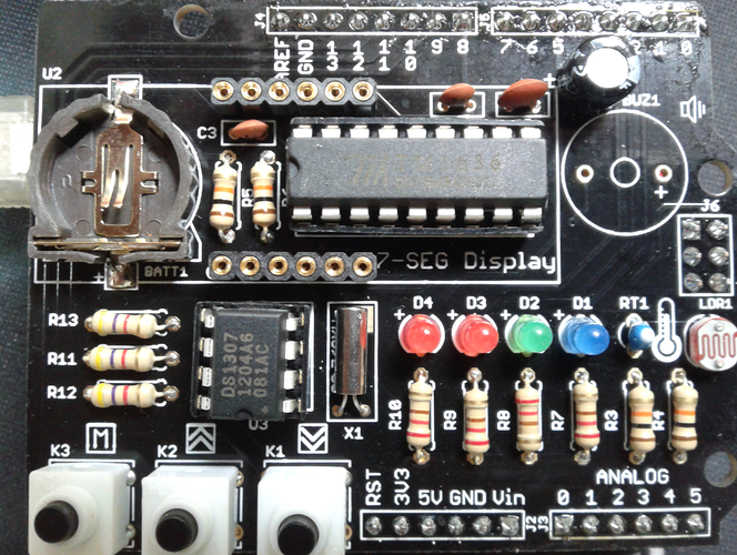
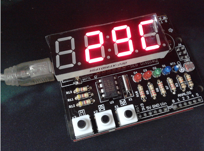
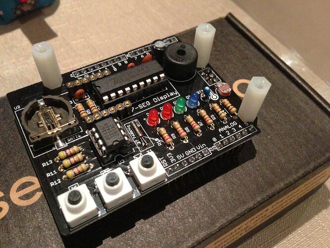
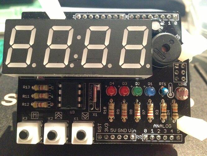
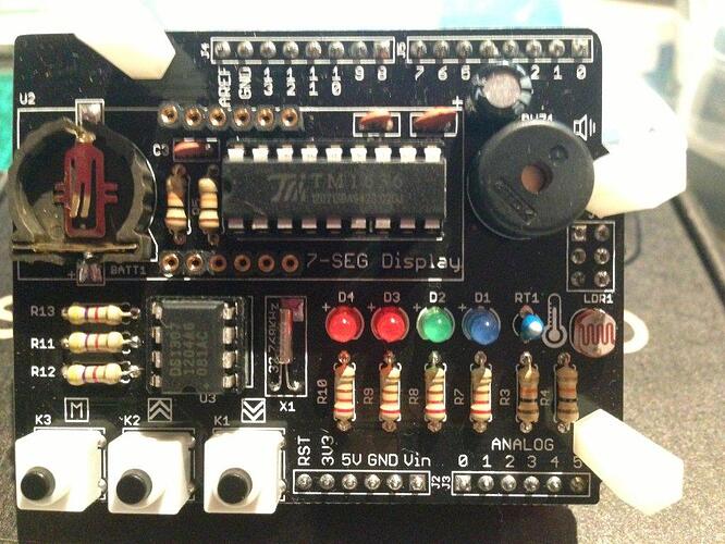
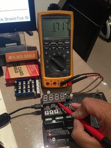
I am having trouble with the new tick tock shield I bought.
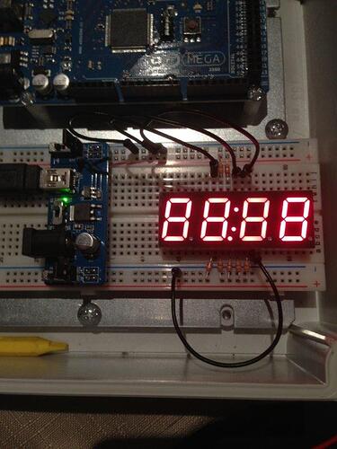
The 7 segments display would not light up.
I ran a few tests using the provided library and confirmed all my buttons, LEDs and buzzer works.
Because the display is not working, I ran resistance tests for the temperature sensor and light sensor and noted resistance changes according to light intensity and temperature. So they are fine.
I did a point to point continuity test according to the schematic and everything has been checked three times.
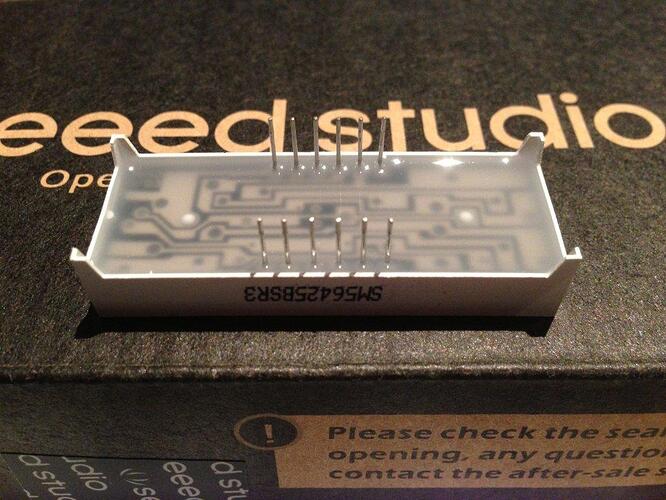
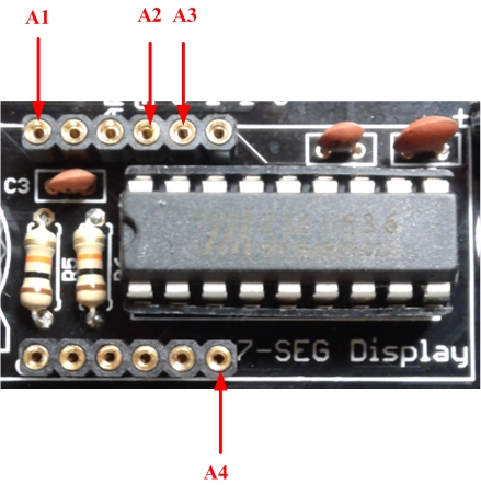
I tested the 7 segments display on a breadboard independently and every segment is working. Only note is that only 1 of the four decimal points is functional by closing DP and A1, it will turns on the middle decimal point. Closing DP and A2 will turn on the middle semicolon, and DP with A3 and A4 have no output.
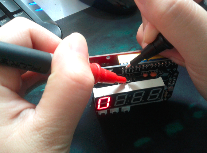
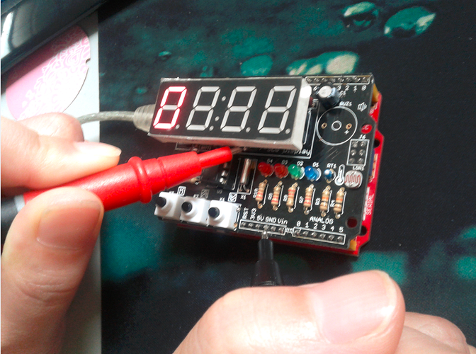
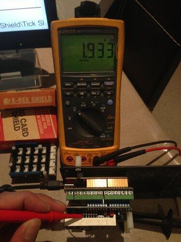
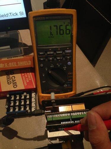
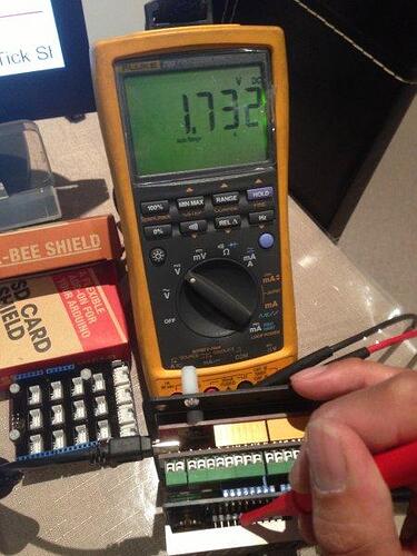
I am getting the following voltage readings when stacked on top of a Seeeduino V3.0 and running the DisplayRTC sketch.
At the DS1307N chip
X1 to GND: 0V
X2 to GND: 2.5V
VBat to GND: 3.1V
5V to GND: 5V
S/O to GND: 5V
SCL to GND: 0.03V
SDA to GND: 5V
At the TM1636 chip
CLK to GND: 5V
DIO to GND: 5V
5V to GND: 5V
5V to GND: 5V
A1, A2, A3 and A4 to GND: 5V
A, B, C, D, E , F, G and DP to GND: 0V
The only component I could not test is the 32.768kHz crystal as I don’t have a scope at home. The instruction suggested soldering the crystal to the PCB pad, and it may suffered heat damage, even my soldering station was set to 330DegC.
Lastly, I compared the capacitors value for C3 and C4 (1nF or 102) with the Titan Micro Electronics Tm1636 datasheet TM1636_V1.2.pdf (321 KB) and found they recommended 0.1nF (101) instead for the CLK and DIO lines. Can someone please verify if the capacitance value is correct?
Any assistance will be much appreciated. Thank you.
Regards,
Vincent
