Having the microphone next to the speaker is not a great layout for moving this into a 3D printed, phone shaped device. Has anyone looked into removing the microphone and using a few inches of wire to relocate it?
Hi David ,
we’ve put filter in the circuit to avoid interference between the speaker and the microphone.
But if you are going to separate these two, it would be easier if you remove the speaker instead of microphone.
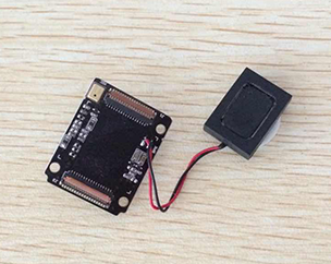
It’s not clear from the above instruction, but the speaker is hot-glued onto the board, so with a gentle twist, it does come off.
Would love to hear a suggestion as to how to remove and shift the microphone though - or if there’s a way I can add a separate mic via the GSM breakout board.
You can add your own microphone and speaker.
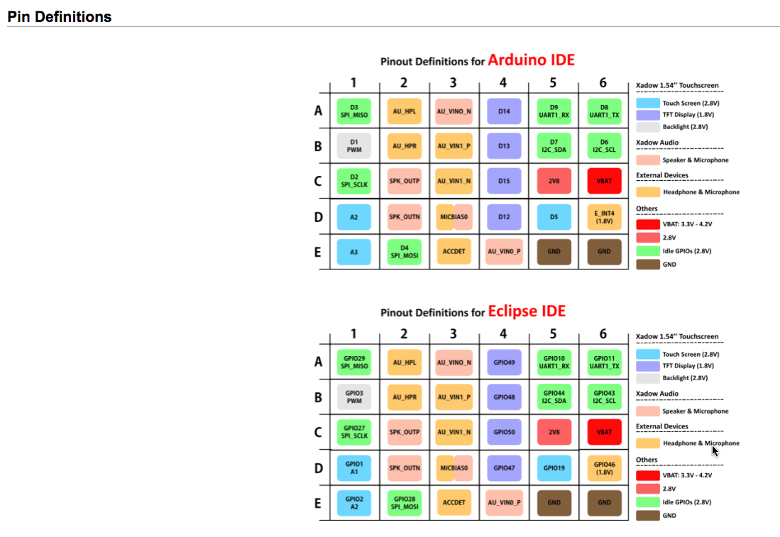
Go to this Wiki page: seeedstudio.com/wiki/Xadow_G … efinitions
There you will find the Pin Definitions for the speaker and microphone connections.
I need more help than just the pinouts (including attachment with screenshot with this post).
According to the legend in the diagram there’s “Xadow Audio/Speaker & Microphone” and “External Devices/Headphone & Microphone”).
Assuming “Xadow Audio”, using the color coding on the diagram the labels are:
C2: SPK_OUTP (I’m assuming order isn’t important, although I’ll switch between to check)
D2: SPK_OUTN
Now according to the color coding, there are FOUR pins in the indicatedcolor:
A3: AU_VIN0_N
D3: MICBIA50
D6: GPIO4646 (1.8V)
E4: AU_VIN0_P
Two questions from here:
- What microphones can I use? I was thinking something like: sparkfun.com/products/9964
- OR could I somehow rig up a headphone/microphone jack similar to what most cell phones have?
Charlie in Houston
3rd way sounds better: I assume that little mic is an electret mic, not a “classic” one. I’m still at the inspection phase, but if I would make a custom mic-speaker board, I’d solder a new small electret mic on a ribbon cable to the breakout board and leave the speaker there. Also hot air gun the old mic down.
To clarify, the breakout board can be daisy-chained behind the audio board, and only the pin-outs for microphone used, keeping the existing speaker intact?
Also, can I echo Charlie’s request for more details than the pin-out diagram. Would love to see some more detailed description or tutorial on moving the mic.
First, if you mean having 2 mics parallell by daisy-chaining, yes, it’s technically possible, but prepare for unforeseen consequences. If you just remove the original mic and have a new on the breakout, than all lights are green, it’s safe to do!
And everything is accessible via eagle schematics. If more people are eager to change the mic but not technical enough to do it, I would happily make a tutorial.
I’ll soon check the schematics and return with a detailed answer.
So, the detailed answer:
- the previously mentioned sparkfun microphone seems good. Bulky, I would use the slightly more expensive, INMP401-based one, because it’s much smaller, but feel free to choose.
- the Xadow Audio has lot of extra stuff like ESD-protection, filter capacitors and inductors, they probably have really good reasons why are they used, try to make a similar setup for your mic.
- sadly I don’t own an oscilloscope (and also don’t have one of the mentioned mic boards) so I can’t 10000% tell, whether the signal levels are good or not. If the supply voltage is not super-high that could fry the input, then it’s safe, just don’t forget the coupling capacitor, and you can experiment with a protoboard + breakout board combo, if you disconnect the original audio board.
Yeah, I picked up the Mems Microphone board you mentioned, but am a little unclear about this part:
So you mean I’ll need to insert a cap to reduce the noise on the input voltage - to isolate the microphone response? Something like 10 uF capacitor?
So you mean I’ll need to insert a cap to reduce the noise on the input voltage - to isolate the microphone response?
Noooo, check the schematics, I hope you can read them. The microphone output and the board input is not connected directly, they have a small capacitor (probably ceramic or other nonpolarized, 10-100 nF) inbetween, in series, so the signal DIFFERENCE (the dv in physics language) goes on the mic input.
I am looking for code to adjust the Microphone Gain via software, at least it is mentioned in the tech brief. On the linkit one any electret mic on the 3.3v line and a 1k ohm seems to work just fine, and it does not need a pre-amp anyhow i have a similar problem because i do need it to be more sensitive but if i dont need a pre-amp it really would be wonderful.
maybe you guys should check and see if the chips actually does have an built in adjust Gain function “and let me know” maybe simpler question is "has anybody heard of this built in function for the linkit one or any other platform ???
thank you
Louie.