It is solved. Supplying it through battery is OK, supplying it from +5V Vusb pin causes 4mA consumption.
I am already working on my application.
It is solved. Supplying it through battery is OK, supplying it from +5V Vusb pin causes 4mA consumption.
I am already working on my application.
Good for you.
The on-board battery charge controller consumes a lot of current when powered from the 5V pin or USB connector.
Looks like, yes, still, can’t fathom how that chip managed to consume 4mA. Yet here we are, Thanks for idea!
According to the datasheet, the current consumption of the charge controller BQ25100 is 0.75mA.
There may be other causes for the 4 mA.
edit
When the battery is not connected, the charging terminal falls below 4.2V, so the BQ25100 attempts to charge the battery until it reaches 4.2V. The operating current at this time would be about 4 mA.
Heyy guys
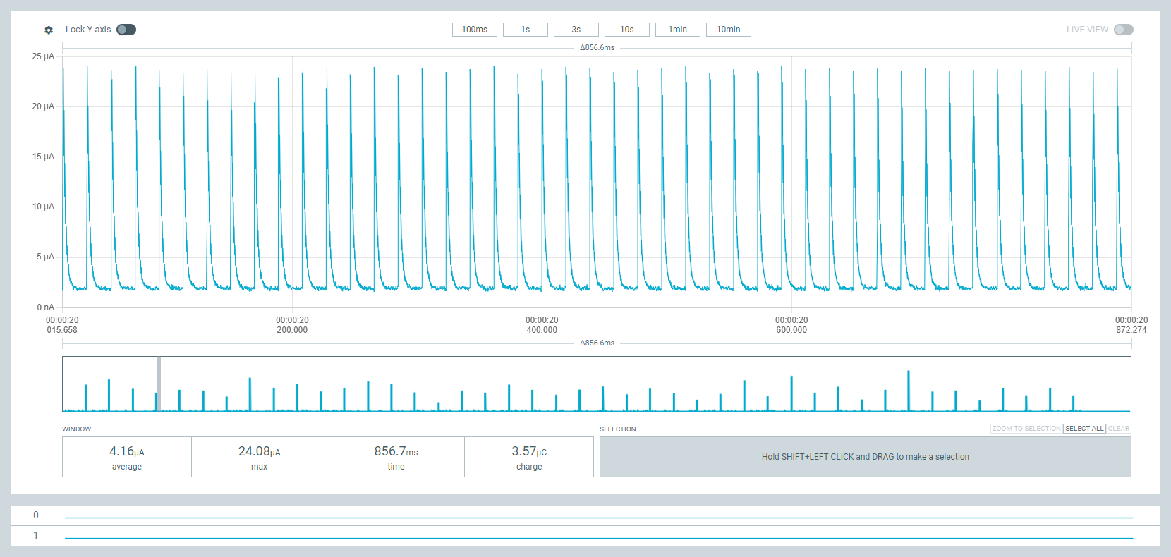
facing an issue observe 5 spikes every 100ms from 2uA to 23uA unable to understand whats the issue
i tried multiple ways , those didnt worked i cimmented them
here is following snipet
//----------------------------------------------------------------------------------------------

// BSP : Seeed nRF52 Borads 1.1.1

// Board : Seeed nRF52 Boards / Seeed XIAO nRF52840 Sense

// important : need for Serial.print() <Arduino.h> <Adafruit_TinyUSB.h>

// \Arduino15\packages\Seeeduino\hardware\nrf52\1.1.1\libraries\Bluefruit52Lib\src

//----------------------------------------------------------------------------------------------

// 2023/07/07

// Central sketch : nRF52_XIAO_LightSleepAdvScan_central.ino

// Need to be deleted /Documents/Arduino/libraries/SdFat

#include <nrf_rtc.h>

#include <Arduino.h>

//#include <Adafruit_TinyUSB.h>   // For Serial.print()

#include <bluefruit.h>          // \Arduino15\packages\Seeeduino\hardware\nrf52\1.1.1\libraries\Bluefruit52Lib\src

#include <Adafruit_SPIFlash.h>  // Need to be deleted /Documents/Arduino/libraries/SdFat

#define SLEEP_TIME  30          // Sleep time [sec]

//#define SLEEP_TIME 30   // Sleep time [sec]

Adafruit_FlashTransport_QSPI flashTransport;

//uint8_t timeout = 5;

void setup() {

// Serial port initialization

//Serial.begin(115200);

//while ((!Serial) && (timeout)){

//   delay(1000);

//   timeout–;

// Enable DC-DC converter

NRF_POWER->DCDCEN = 1;  // Enable DC/DC converter for REG1 stage

// Sleep QSPI flash

flashTransport.begin();

flashTransport.runCommand(0xB9);  // enter deep power-down mode

flashTransport.end();

//NRF_UART0->ENABLE = 0;  // Disable UART

//NRF_SPI0->ENABLE = 0;   // Disable SPI

//NRF_TWI0->ENABLE = 0;   // Disable I2C

//Bluefruit.begin();

//Bluefruit.Advertising.start();

//Bluefruit.Advertising.stop();

//Bluefruit.end();

//RTC initialization

initRTC(32768 * SLEEP_TIME);    // SLEEP_MTIME [sec]

SysTick->CTRL &= ~SysTick_CTRL_ENABLE_Msk;

// Initialization of Bruefruit class

// Bluefruit.begin();

//Bluefruit.setTxPower(4);  // Check bluefruit.h:151 for supported values

//Bluefruit.autoConnLed(false); // turn off LED to save power   Sleep Current 4uA

//  Bluefruit.setConnLedInterval(50); // Should not be used, Sleep current 300uA

suspendLoop();

// Serial.println(“End of initialization”);

}

//*************************************************************************************************************

void loop() {

// Bluefruit.Advertising.stop();

//delay(5000);

//digitalWrite(LED_BLUE, LOW);  // turn the LED on (HIGH is the voltage level)

//delay(5000); //Led on                     // light for 5 seconds, but the rtc in the background keeps running. → light off only for 25 seconds

//digitalWrite(LED_BLUE, HIGH);

//enterLowPowerState();

// delay(SLEEP_TIME * 1000);

// Sleep

__WFI();

__SEV();

__WFI();

// System ON Sleep by FreeRTOS

}

//**************************************************************************************************************

// RTC initialization

void initRTC(unsigned long count30)

{

// See “6.22 RTC - Real-time counter 6.22.10 Registers”

NRF_CLOCK->TASKS_LFCLKSTOP = 1;

NRF_CLOCK->LFCLKSRC = 1;      // select LFXO

NRF_CLOCK->TASKS_LFCLKSTART = 1;

while(NRF_CLOCK->LFCLKSTAT != 0x10001)

NRF_RTC2->TASKS_STOP = 1;      // stop counter

NRF_RTC2->TASKS_CLEAR = 1;     // clear counter

NRF_RTC2->PRESCALER = 0;       // set counter prescaler, fout=32768/(1+PRESCALER) 32768Hz

NRF_RTC2->CC[0] = count30;     // set value for TRC compare register 0

NRF_RTC2->INTENSET = 0x10000;  // enable interrupt CC[0] compare match event

NRF_RTC2->EVTENCLR = 0x10000;  // clear counter when CC[0] event

NVIC_SetPriority(RTC2_IRQn,3); // Higher priority than SoftDeviceAPI

NVIC_EnableIRQ(RTC2_IRQn);     // enable interrupt

NRF_RTC2->TASKS_START = 1;     // start Timer

}

//**************************************************************************************************************

// RTC interrupt handler

extern “C” void RTC2_IRQHandler(void)

{

if ((NRF_RTC2->EVENTS_COMPARE[0] != 0) && ((NRF_RTC2->INTENSET & 0x10000) != 0)) {

NRF_RTC2->EVENTS_COMPARE[0] = 0;  // clear compare register 0 event

NRF_RTC2->TASKS_CLEAR = 1;        // clear counter

//intFlag = true;

//digitalWrite(LED_RED, LOW);

//delayMicroseconds(10000);      // for LED

//digitalWrite(LED_RED, HIGH);

}

}
following is ouput observed on PPK
I think the DC/DC converter may be working.
Please use </> when you post your code.
For example, if you want XIAO to wake up every 30 seconds, you should write delay(30000); instead of using RTC, which will reduce the sleep current.
Hi there,
As @msfujino indicates use the delay or the Sleep is the Zyphur using the RTC in System on sleep.
My .02 after scanning some old threads, in anticipation of the Xiao that uses battery like a “Camel in the Desert.” ![]()
![]()
When it Drops, Ninja’s will be get’tin “Sturdy” ![]()
Xiao4Ever ![]()
GL ![]() PJ
PJ ![]()
Hi there, I am a bit late to the party but I am at my wits end because my measurements look nothing like the things I see here.
As a demo I used this sketch:
because @msfujino provided his measurements.
My measurements look like this 100k samples/sec, 3.6V to battery pads:
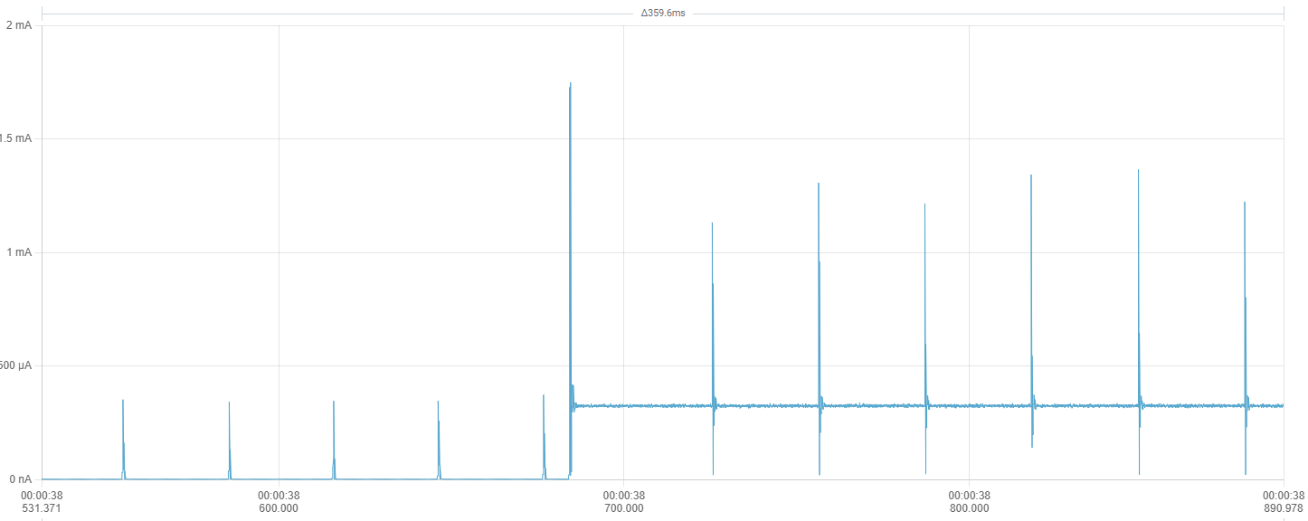
Every 30ms i get heavy spikes. These spikes are about 400uA while in light sleep (delay) and up to 1mA during LED on. While spikes of a few dozen uA seem to be normal, these are waaay of the chart.
Even in deep sleep (adding NRF_POWER->SYSTEMOFF = 1; to the end of setup) the 400uA spikes are there but only every 200ms
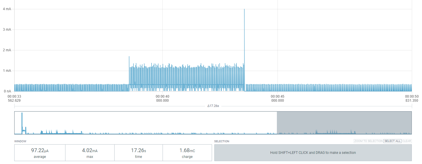
While the average of the sleep period is about 4uA (matching msfujino´s value) the “LED on” period averages at about 320uA (about double of msfujino´s value).
My original setup was using PlatformIO but in my desperation of narrowing this down i also tried ArduinoIDE with Board 1.1.10
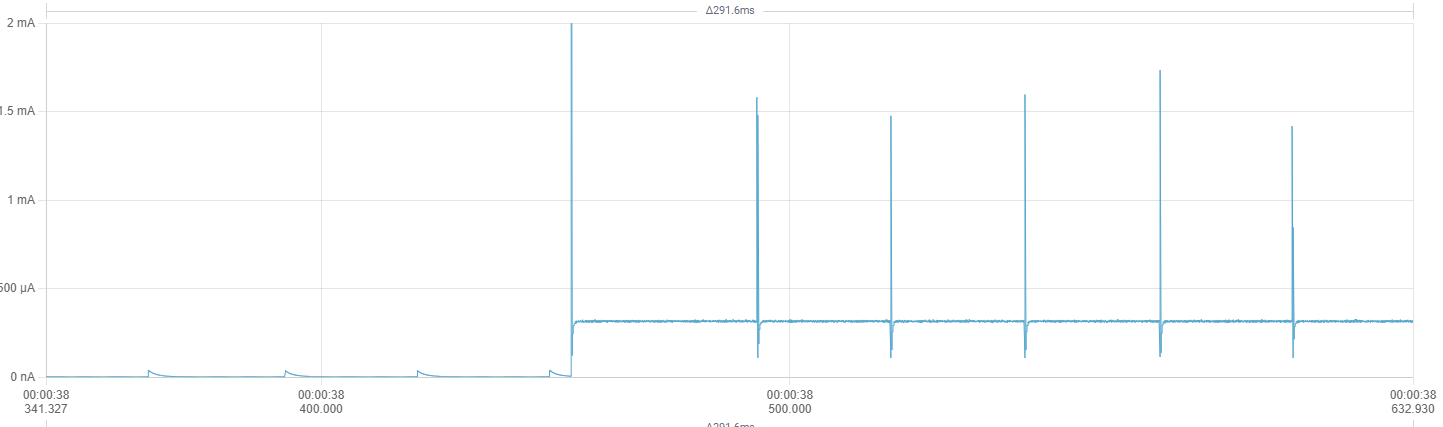
The only thing that helps a bit is providing 3.3v directly to the 3.3v Pin instead of using the battery pads. This reduces the light-sleep spikes to more normal 40uA. But the 1mA active-spikes are still there:
I also tried:
Has anyone an idea how to bring these spikes down?
Hi there,
SO there is a Ton of Nuance to Sleep we all have learned, even the BSP, the Process , where you connect what , ALL of it…
Keep digging you’ll get there. The Rtos does some stuff too. Check this thread I think you’ll find a similar post about the spikes and what the user did to mitigate them. YMMV ![]()
Read all of the Power ninja’s ![]() posts too @msfujino. he’s got the most receipts and testing under his cap.
posts too @msfujino. he’s got the most receipts and testing under his cap. ![]()
HTH
GL ![]() PJ
PJ
ThePradox,
Let us know your ArduinoIDE sketch and BSP version and connections.
We will try to measure it.
EDIT
Current consumption varies depending on the LEDs to be lit. My data was for green LED.
Red:720uA, Green:120uA, Blue:320uA.
ArduinoIDE: 2.3.6, BSP: 1.1.10, nothing attached just PPK2 3.6V to the Battery Pads
Using this sketch:
#include <Arduino.h>
#include <Adafruit_TinyUSB.h>   // For Serial.print()
#include <Adafruit_SPIFlash.h>  // Need to be deleted /Documents/Arduino/libraries/SdFat

#define SLEEP_TIME 30   // Sleep time [sec]

Adafruit_FlashTransport_QSPI flashTransport;

void setup() {
  delay(2000);

  // Enable DC-DC converter
  NRF_POWER->DCDCEN = 1;  // Enable DC/DC converter for REG1 stage

  // Sleep QSPI flash
  flashTransport.begin();
  flashTransport.runCommand(0xB9);  // enter deep power-down mode
  flashTransport.end();

  //NRF_POWER->SYSTEMOFF = 1;
}

//*************************************************************************************************************
void loop() {

  digitalWrite(LED_BLUE, LOW);  // turn the LED on (HIGH is the voltage level)
  delay(5000);                      // light for 5 seconds, but the rtc in the background keeps running. --> light off only for 25 seconds
  digitalWrite(LED_BLUE, HIGH);
  delay(SLEEP_TIME * 1000);           // System ON Sleep by FreeRTOS
}
Do you get the same 400 uA spikes during light-sleep?
A 300uA spike is visible with a period of 22mS.
Thank you, so this is normal. I was just very irritated because the screenshots in this thread never showed this
This has been a very helpful thread, and I’d like to thank everyone for their contributions. I am using the Xiao nRF52840 in an anemometer to record mean wind-speed and gusts, sending the data back to a hub using LoRa. It will be battery powered and mounted on my roof, so I am keen to get low power consumption for long battery life.
I am using PlatformIO in VSCode with the Arduino framework. I had trouble getting the MCU to go in to POWER ON sleep until I found a suggestion by daCoder to use semaphores, which worked very well. Using unmodified libraries, these are the current consumption figures I have measured with the board powered through the battery terminals (I am using 3 lithium AA batteries, so max. voltage is about 5V):
PlatformIO ini
[env:seeed_xiao_nrf52840]
platform = https://github.com/Seeed-Studio/platform-seeedboards.git
board = seeed-xiao-afruitnrf52-nrf52840
framework = arduino
lib_deps =
	adafruit/Adafruit SPIFlash@^5.1.1
monitor_speed = 115200
upload_speed = 115200
main.zip (1.7 KB)
Caution is required when connecting batteries other than LiPo batteries rated at 3.7V (max 4.2V) to the battery pad. If USB is connected, the battery will be charged at 4.2V.
Yes, I avoid having the USB and battery both connected at the same time. I have a Schottky diode in series to protect the battery pack from the charge circuit just in case. I’ll remove the diode when complete to get a bit more of the battery capacity as the voltage drop is about 300 mV.
Yes, I have seen that but it also needs a LoRaWAN gateway, further adding to the cost. Also, it is a bit of an eyesore to stick on my chimney! I have a more discrete anemometer for the chimney and the rest goes in the garden. I already have a few sensors and don’t really need LoRaWAN. I am using an ESP32 with SX1262 as a hub and uploading data to a weather service via wifi.
Instead of using a binary semaphore to block the CPU and put Arduino’s underlying FreeRTOS to sleep, direct-to-task notifications are up to 45% faster and use less resources. For applications with intensive interrupt driven wakes, notifications may improve performance and reduce power consumption. They are just as easy to implement as semaphores. See this example.
Decrease RAM Footprint and Accelerate Execution with FreeRTOS Notifications
#include <Arduino.h>
#include <Adafruit_SPIFlash.h>

const unsigned long kSerialSpeed = 115200;

// Flash Class instance - used to put flash to sleep and save power
Adafruit_FlashTransport_QSPI flashTransport;

// task handle for direct-to-task notifications
static TaskHandle_t xTaskToNotify = NULL;

volatile bool flag_clock_interrupt = false;

/**
 * Interrupt service routine for RTC timer.
 */
extern "C" void RTC2_IRQHandler(void)
{
  if ((NRF_RTC2->EVENTS_COMPARE[0] != 0) && ((NRF_RTC2->INTENSET & 0x10000) != 0)) {
    // disable interrupts for critical code
    UBaseType_t uxSavedInterruptStatus = taskENTER_CRITICAL_FROM_ISR();

    NRF_RTC2->EVENTS_COMPARE[0] = 0;  // clear compare register 0 event
    NRF_RTC2->TASKS_CLEAR = 1;        // clear counter

    flag_clock_interrupt = true;

    // re-enable interrupts
    taskEXIT_CRITICAL_FROM_ISR(uxSavedInterruptStatus);

    BaseType_t xHigherPriorityTaskWoken = pdFALSE;
    vTaskNotifyGiveFromISR(xTaskToNotify, &xHigherPriorityTaskWoken );
    portYIELD_FROM_ISR(xHigherPriorityTaskWoken);  // immediate context switch without waiting for next RTOS tick
  }
}

/**
 * Initialise low frequency RTC and configure interrupt
 * @param[in] RTCcount time interval in seconds * 1024
 */
void InitialiseLFRTC(const uint32_t& RTCcount)
{
  NRF_CLOCK->TASKS_LFCLKSTOP = 1;
  NRF_CLOCK->LFCLKSRC = 1;       // select LFXO
  NRF_CLOCK->TASKS_LFCLKSTART = 1;
  while(NRF_CLOCK->LFCLKSTAT != 0x10001)

  NRF_RTC2->TASKS_STOP = 1;      // stop counter
  NRF_RTC2->TASKS_CLEAR = 1;     // clear counter
  NRF_RTC2->PRESCALER = 31;      // set counter prescaler, fout=32768/(1+PRESCALER) 1024Hz
  NRF_RTC2->CC[0] = RTCcount;    // set value for TRC compare register 0
  NRF_RTC2->INTENSET = 0x10000;  // enable interrupt CC[0] compare match event
  NRF_RTC2->EVTENCLR = 0x10000;  // clear counter when CC[0] event
  NVIC_SetPriority(RTC2_IRQn,3); // Higher priority than SoftDeviceAPI
  NVIC_EnableIRQ(RTC2_IRQn);     // enable interrupt
  NRF_RTC2->TASKS_START = 1;     // start Timer
}

/**
 * Flash on-board LED.
 * @param led_colour pin address of LED to flash
 * @param duration duration of LED flash in milliseconds
 * @param num_flashes how many flashes to perform
 */
void FlashLED(const uint32_t& led_colour, const uint32_t& duration, const uint16_t& num_flashes) {
  pinMode(led_colour, OUTPUT);
  for (int i = 0; i < num_flashes; i++) {
    digitalWrite(led_colour, LOW);
    delay(duration);
    digitalWrite(led_colour, HIGH);
    delay(duration);
  }
}

void setup() {
  delay(2000);

  FlashLED(LED_GREEN, 50, 5);

  Serial.begin(kSerialSpeed);
  Serial.println("Starting up.");
  Serial.flush();

  // Use DC-DC converter to save power - best improvement is on high duty cycle
  NRF_POWER->DCDCEN = 1;

  // power down flash - saves a few microamps
  flashTransport.begin();
  flashTransport.runCommand(0xB9);
  delayMicroseconds(5);
  flashTransport.end();

  // power down SPI to prevent wakes
  SPI.end();

  // Configure RTC interrupt interval
  InitialiseLFRTC(1024 * 5);  // 5 second interval

  // Handle for current task. ISR sends message to this to clear CPU block.
  xTaskToNotify = xTaskGetCurrentTaskHandle();

  uint16_t interrupt_counter = 0;

  while(true) {

    ulTaskNotifyTake(pdTRUE, portMAX_DELAY);

    if (flag_clock_interrupt) {
      flag_clock_interrupt = false;
      ++interrupt_counter;
      Serial.print("Timer interrupt: ");
      Serial.println(interrupt_counter);
      Serial.flush();
      FlashLED(LED_BLUE, 10, 1);
    } else {
      Serial.println("Something else woke me up!");
      Serial.flush();
    }

  }
}

void loop() {
}