Type_Z
September 29, 2023, 6:01am
1
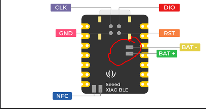
Am wondering what is the pin number of Studio XIAO nRF52840 (Sense) battery pins which are on the back, they are not mentioned in the pinout diagram
i have solder lipo battery to these pins and i want to monitor battery usage via code and want to send info to my android app so that i know how much battery is left so that can be recharged on time.
code
#define VBAT_PIN          (A7)

// 3.0V ADC range and 12-bit ADC resolution = 3000mV/4096
#define VBAT_MV_PER_LSB   (0.73242188F)

// 2M + 0.806M voltage divider on VBAT = (2M / (0.806M + 2M))
#define VBAT_DIVIDER      (0.71275837F)

// Compensation factor for the VBAT divider
#define VBAT_DIVIDER_COMP (1.403F)

int vbat_raw;
uint8_t vbat_per;
float vbat_mv;

void setup(void) {
  Serial.begin(115200);

  analogReference(AR_INTERNAL_3_0);
  analogReadResolution(12);  // Can be 8, 10, 12 or 14
  delay(1);
}

void loop(void) {
  vbat_raw = analogRead(VBAT_PIN);
  vbat_per = mvToPercent(vbat_raw * VBAT_MV_PER_LSB);

  // FIXME: Using C-style cast.  Use static_cast<float>(...)
  // instead  [readability/casting] [4]
  // Remove [readability/casting] ignore from Makefile
  vbat_mv = (float)vbat_raw * VBAT_MV_PER_LSB * VBAT_DIVIDER_COMP;

  Serial.print("ADC = ");
  Serial.print(vbat_raw * VBAT_MV_PER_LSB);
  Serial.print(" mV (");
  Serial.print(vbat_raw);
  Serial.print(") ");
  Serial.print("LIPO = ");
  Serial.print(vbat_mv);
  Serial.print(" mV (");
  Serial.print(vbat_per);
  Serial.println("%)");

  delay(4000);
}

uint8_t mvToPercent(float mvolts) {
  uint8_t battery_level;

  if (mvolts >= 3000) {
    battery_level = 100;
  } else if (mvolts > 2900) {
    battery_level = 100 - ((3000 - mvolts) * 58) / 100;
  } else if (mvolts > 2740) {
    battery_level = 42 - ((2900 - mvolts) * 24) / 160;
  } else if (mvolts > 2440) {
    battery_level = 18 - ((2740 - mvolts) * 12) / 300;
  } else if (mvolts > 2100) {
    battery_level = 6 - ((2440 - mvolts) * 6) / 340;
  } else {
    battery_level = 0;
  }

  return battery_level;
}
so what should be value of VBAT_PIN ?? as the back battery pins have no name mentioned on it.
am using seeed nr52840 standard arduino pacakge not Mbed OS
The following link will answer your questionsGetting Started | Seeed Studio Wiki ’
Battery charging schematic in the section “Q3: What are the considerations when using XIAO nRF52840 (Sense) for battery charging?”
Type_Z
September 30, 2023, 6:15am
3
hmmm ok i checked it however its big confusing not much info about monitoring there . however they mentioned : D14 pin so this mean in my sample code if i set VBAT_PIN to D14 i should get reading ?
thanks
Try the code below.
//----------------------------------------------------------------------------------------------
//Board Library : Seeed nRF52 Borads 1.1.1
//Board Select  : Seeed nRF52 Borads / Seeed XIAO nRF52840 Sense
//----------------------------------------------------------------------------------------------
#include <Arduino.h>
#include <Adafruit_TinyUSB.h>   // for Serial.print()

//Arduino15\packages\Seeeduino\hardware\nrf52\1.1.4\variants\Seeed_XIAO_nRF52840_Sense\variant.cpp
#define PIN_VBAT        (32)  // D32 battery voltage
#define PIN_VBAT_ENABLE (14)  // D14 LOW:read anable
#define PIN_HICHG       (22)  // D22 charge current setting LOW:100mA HIGH:50mA
#define PIN_CHG         (23)  // D23 charge indicatore LOW:charge HIGH:no charge

void setup()
{
  Serial.begin(115200);
  while(!Serial);

  pinMode(PIN_VBAT, INPUT);
  pinMode(PIN_VBAT_ENABLE, OUTPUT);
  pinMode(PIN_HICHG, OUTPUT);
  pinMode(PIN_CHG, INPUT);

  digitalWrite(PIN_VBAT_ENABLE, LOW); // VBAT read enable
  digitalWrite(PIN_HICHG, LOW);       // charge current 100mA

  // initialise ADC wireing_analog_nRF52.c:73
  analogReference(AR_DEFAULT);        // default 0.6V*6=3.6V  wireing_analog_nRF52.c:73
  analogReadResolution(12);           // wireing_analog_nRF52.c:39

}

void loop()
{
  int vbatt = analogRead(PIN_VBAT);
  Serial.print(vbatt, HEX);
  Serial.print("    ");
  Serial.print(2.961 * 3.6 * vbatt / 4096);   // Resistance ratio 2.961, Vref = 3.6V
  Serial.print("    ");
  Serial.println(digitalRead(PIN_CHG));       // 0:charge, 1:discharge

  delay(1000);
}
Type_Z
September 30, 2023, 6:43am
5
msfujino:
//----------------------------------------------------------------------------------------------
//Board Library : Seeed nRF52 Borads 1.1.1
//Board Select  : Seeed nRF52 Borads / Seeed XIAO nRF52840 Sense
//----------------------------------------------------------------------------------------------
#include <Arduino.h>
#include <Adafruit_TinyUSB.h>   // for Serial.print()

//Arduino15\packages\Seeeduino\hardware\nrf52\1.1.4\variants\Seeed_XIAO_nRF52840_Sense\variant.cpp
#define PIN_VBAT        (32)  // D32 battery voltage
#define PIN_VBAT_ENABLE (14)  // D14 LOW:read anable
#define PIN_HICHG       (22)  // D22 charge current setting LOW:100mA HIGH:50mA
#define PIN_CHG         (23)  // D23 charge indicatore LOW:charge HIGH:no charge

void setup()
{
  Serial.begin(115200);
  while(!Serial);

  pinMode(PIN_VBAT, INPUT);
  pinMode(PIN_VBAT_ENABLE, OUTPUT);
  pinMode(PIN_HICHG, OUTPUT);
  pinMode(PIN_CHG, INPUT);

  digitalWrite(PIN_VBAT_ENABLE, LOW); // VBAT read enable
  digitalWrite(PIN_HICHG, LOW);       // charge current 100mA

  // initialise ADC wireing_analog_nRF52.c:73
  analogReference(AR_DEFAULT);        // default 0.6V*6=3.6V  wireing_analog_nRF52.c:73
  analogReadResolution(12);           // wireing_analog_nRF52.c:39

}

void loop()
{
  int vbatt = analogRead(PIN_VBAT);
  Serial.print(vbatt, HEX);
  Serial.print("    ");
  Serial.print(2.961 * 3.6 * vbatt / 4096);   // Resistance ratio 2.961, Vref = 3.6V
  Serial.print("    ");
  Serial.println(digitalRead(PIN_CHG));       // 0:charge, 1:discharge

  delay(1000);
}
ok great thanks
Hello Everybody,
Where can I find the blue LED associated with 14?
VBAT_ENABLE is associated with 14 (P0.14) and LED_BLUE is associated with 6 (P0.06). You need to refer to the following files and schematics.
C:\Users\username\AppData\Local\Arduino15\packages\Seeeduino\hardware\nrf52\1.1.9\variants\Seeed_XIAO_nRF 52840_Sense\variant.cpp and variant.h
Thanks msfujino.
Refer to “PinDescription g_APinDescription” in variant.cpp.
VBAT is associated with P0_14 and LED BLUE is associated with P0_6.#define PIN_VBAT_ENABLE (32u)” means the 32nd from the top (starting from zero) and “#define LEDB (14u)” means the 14th from the top.
Note: The comment D# number in “PinDescription g_APinDescription” is wrong.
yes, I understood. But when I put low VBAT_ENABLE the blue led light on :-).
PR
What is the BoardSupportPackage you are using? Is it “Seeed nRF Boards”? Or “Seeed nRF52 mbed-enabled Bloard”?
Show us your sketch.
In Boards - tools menu is selected Seeed nRF52 Boards with and after Seeed XIAO nRF52840 Sense
Try this sketch.
//----------------------------------------------------------------------------------------------
//Board Library : Seeed nRF52 Borads 1.1.8
//Board Select  : Seeed nRF52 Borads / Seeed XIAO nRF52840 Sense
//----------------------------------------------------------------------------------------------
#include <Arduino.h>
#include <Adafruit_TinyUSB.h>   // for Serial.print()

//Arduino15\packages\Seeeduino\hardware\nrf52\1.1.8\variants\Seeed_XIAO_nRF52840_Sense\variant.cpp
#define PIN_VBAT        (32)  // D32 battery voltage
#define PIN_VBAT_ENABLE (14)  // D14 LOW:read anable
#define PIN_HICHG       (22)  // D22 charge current setting LOW:100mA OPEN:50mA
#define PIN_CHG         (23)  // D23 charge indicatore LOW:charge HIGH:no charge

void setup()
{
  Serial.begin(115200);
  while(!Serial);

  pinMode(PIN_VBAT_ENABLE, OUTPUT);
  digitalWrite(PIN_VBAT_ENABLE, LOW); // VBAT read enable

//  pinMode(PIN_HICHG, OUTPUT);         // charge current 100mA
//  digitalWrite(PIN_HICHG, LOW);       // charge current 100mA
  pinMode(PIN_HICHG, INPUT);          // charge current 50mA

  pinMode(PIN_CHG, INPUT);            // charge indicatore LOW:charge HIGH:discharge

  // initialise ADC wireing_analog_nRF52.c:73
  analogReference(AR_DEFAULT);        // default 0.6V*6=3.6V  wireing_analog_nRF52.c:73
  analogReadResolution(12);           // wireing_analog_nRF52.c:39
}

void loop()
{
  int vbatt = analogRead(PIN_VBAT);
  Serial.print(vbatt, HEX);
  Serial.print("    ");
  Serial.print(2.961 * 3.6 * vbatt / 4096);   // Resistance ratio 2.961, Vref = 3.6V
  Serial.print("    ");
  Serial.println(digitalRead(PIN_CHG));       // 0:charge, 1:discharge

  delay(1000);
}
msfujino:
//----------------------------------------------------------------------------------------------
//Board Library : Seeed nRF52 Borads 1.1.8
//Board Select  : Seeed nRF52 Borads / Seeed XIAO nRF52840 Sense
//----------------------------------------------------------------------------------------------
#include <Arduino.h>
#include <Adafruit_TinyUSB.h>   // for Serial.print()

//Arduino15\packages\Seeeduino\hardware\nrf52\1.1.8\variants\Seeed_XIAO_nRF52840_Sense\variant.cpp
#define PIN_VBAT        (32)  // D32 battery voltage
#define PIN_VBAT_ENABLE (14)  // D14 LOW:read anable
#define PIN_HICHG       (22)  // D22 charge current setting LOW:100mA OPEN:50mA
#define PIN_CHG         (23)  // D23 charge indicatore LOW:charge HIGH:no charge

void setup()
{
  Serial.begin(115200);
  while(!Serial);

  pinMode(PIN_VBAT_ENABLE, OUTPUT);
  digitalWrite(PIN_VBAT_ENABLE, LOW); // VBAT read enable

//  pinMode(PIN_HICHG, OUTPUT);         // charge current 100mA
//  digitalWrite(PIN_HICHG, LOW);       // charge current 100mA
  pinMode(PIN_HICHG, INPUT);          // charge current 50mA

  pinMode(PIN_CHG, INPUT);            // charge indicatore LOW:charge HIGH:discharge

  // initialise ADC wireing_analog_nRF52.c:73
  analogReference(AR_DEFAULT);        // default 0.6V*6=3.6V  wireing_analog_nRF52.c:73
  analogReadResolution(12);           // wireing_analog_nRF52.c:39
}

void loop()
{
  int vbatt = analogRead(PIN_VBAT);
  Serial.print(vbatt, HEX);
  Serial.print("    ");
  Serial.print(2.961 * 3.6 * vbatt / 4096);   // Resistance ratio 2.961, Vref = 3.6V
  Serial.print("    ");
  Serial.println(digitalRead(PIN_CHG));       // 0:charge, 1:discharge

  delay(1000);
}
thanks! the blue led is off.
#include “LSM6DS3.h”#include “Wire.h”#include <ArduinoBLE.h>#include <Arduino.h>#include “SPI.h”#include <Adafruit_TinyUSB.h>
#define BAT_HIGH_CHARGE 13#define BAT_CHARGE_STATE 23#define VIBRATION_PIN 0#define VBAT_ENABLE 14#define INV_PI (0.31830988618379F) // 1/pigreco#define CLEAR_STEP true#define NOT_CLEAR_STEP false#define int2Pin PIN_LSM6DS3TR_C_INT1 // for weakup after double tap when in deep sleep mode
You cannot use <ArduinoBLE.h> with your BoardSupportPackege. Use <bluefruit.h> instead.
msfujino,
PR
Since the topic has strayed from the title of the thread, I responded this time by email. If it continues further, I ask that a new thread be started.
edit:
There are two types of BSPs for nRF52840.
BSP : Seeed nRF52 Borads 1.x.x
If you like ArduinoBLE.h you need to use Seeed nRF52 mbed-enabled Borads.
BLE applications can be built with either ArduinoBLE or bruefruit by following examples, with some differences. However, if you want to reduce power consumption by putting the device to sleep, you will need to use bruefruit.