I have a Stalker set up to log the LED pulse from an electricity meter. The sensor is an LLS05-A http://www.futurlec.com/Light_Sensor.shtml connected via digital pin 3, 5V & GND with a 10K resistor between Vout and GND.
It all works very well running off a 9V PP3 battery connected directly to Stalker. I would like to use the Seeedstudio Solar shield to provide the power via a LiPo battery but there are problems. When powered from the Solar shield (battery or USB) the sensor is flickering on and off very quickly causing an incorrect data count. The project has an LED on analog pin 0 which cycles between on & off each time a pulse is detected from the meter LED via the sensor. This LED allows me to ‘see’ the sensor tripping incorrectly and the data logged shows very high values to confirm this.
The sensor is work via an interupt: attachInterrupt(1, wattSensorInterrupt, RISING);
Any idea what would be causing this & how I could fix it?
Hi,
Do you have a DSO , I guess that may be the 5V from the solar charger is not so stable , so it will case the edge trigger to the interrupt - see your code you using Rising edge for enter interrupt.
And the circuit you used is not so reliable even use the Power JET. It’s not suitable to use a digital interrupt to catch a analog change , it may cause some uncertainty error.
Thanks for the info - unfortunately no DSO, perhaps I need to purchase one
I’m not very experienced with electronics -would you be able to recommend a sensor, circuit and code/sketch method for the application of counting LED pulses form an electricity meter?
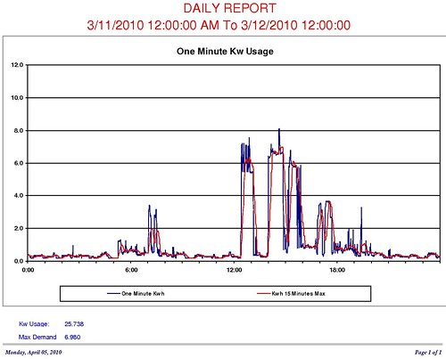
cambo - It looks like you might be using my sketch from the Arduino forum. I have had some false readings due to background light levels using RISING in the interrupt and have had better responses using FALLING. I am using a light to voltage sensor TAOS Photodiode part number TSL267-LF from Mouser: http://www.mouser.com/ProductDetail/TAOS/TSL267-LF/?qs=rBDwU0K8fVpc2GQ0WesZ9g%3d%3d. It gives a nice dependable square wave but is very sensitive to ambient light so I have had to put a cover over my meter to keep light out. I have been using the Stalker for recording power use for several months and it has not missed any pulses. Here is a example of a daily usage chart:
I bought a JYE Tech oscilloscope and it has helped me a lot for looking at the signal. I would recommend getting a oscillscope if you are going to do much with electronics, it would help for looking at the signal from the solar shield and might help you solve that problem. I have some pictures of the response so I will post them if I can get them uploaded.
I see that a new Stalker has been released using the ATmega 328. Once they are available in the States I will update the sketches using the increased capabilities of the 328.
I will look into the TAOS sensor - is it simply wired to the Stalker or is there a circuit to make? With the sensor facing you: left pin goes to GND, middle pin goes to 5V & right pin goes to Digital pin 3…?
The JYE scope looks interesting - as does the Seeeduino version
The sensor is wired as you have written. I have used other sensors similiar to yours and they have worked but the resistance values need to be adjusted to optimize the response to the IR signal. I have tested my sketch by connecting a IR LED to the Stalker and modifying the sketch to include the code from the BlinkWithoutDelay example to simulate the IR output from the smart meter. You also do not want to have any Delay() statements in the sketch because you will miss pulses that occur during the delay. The BlinkWithoutDelay sketch demonstrates how to delay the sketch without stopping processing the interrupts.
I need to try some IR band pass filters to see if it is possible to block visible light so that it is not neccessary to cover the electrical meter. Black and Decker makes a power meter and its sensor simply clamps around the meter. Info about the Black and Decker can be found at: http://www.energyfederation.org/consumer/default.php/cPath/4209_3434
Thanks for the info - I have tried to source the TSL267-LF but nothing locally. Do you know if the TSL261R-LF gb.mouser.com/ProductDetail/TAOS … s%2fijfHXp would serve equally well?.. I tried to spot the difference without luck?
It took some looking but it looks like the differences are the Rise/Fall times and Responsivity. A summary table can be found on the taosinc.com website at the following link: http://www.taosinc.com/Productfamily.aspx?id=1&SD=ltv. The models we are looking at are on the second page.
I really do not know which would work better or if there are any practical differences for our application. My guess is that both would work fine for the low frequency that we are measuring.